B.2 Parameter Table
YASKAWA TM.V1000.01 V1000 Drive Installation & Start-Up Manual (Preliminary 01-19-07) 395
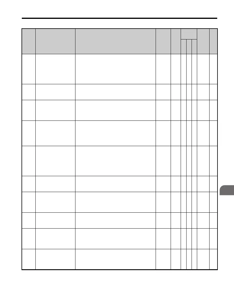
Parameter List
B
L8-10
Heatsink Cooling Fan
Operation Selection
Controls the heatsink cooling fan operation.
0: Fan On-Run Mode - Fan will operate only
when the drive is running and for L8-11
seconds after RUN is removed.
1: Fan always on - Cooling fan operates
whenever the drive is powered up.
0,1 0 A A A 4B6 —
L8-11
Heatsink Cooling Fan
Operation Delay
Time
This parameter sets the delay time for the
cooling fan to shut off after the run command
is removed when L8-10 = 0.
0 to 300 60 s A A A 4B7 —
L8-12
Ambient Temperature
Setting
Adjust the drive overload (OL2) protection
level when the drive is installed in an
environment that exceeds its ambient
temperature rating.
40 to 60
40
°C
AAA 4B8 —
L8-15
OL2 Characteristics
Selection at Low
Speeds
Assists in protecting the output transistors from
overheating when output current is high and
output frequency is low (6Hz and less).
0: Disabled - L8-16 and L8-17 are disabled.
1: Enabled - L8-16 and L8-17 are enabled.
0,1 1 A A A 4BB —
L8-18 Soft CLA Selection
Enables and disables the software current limit
function. This parameter does not typically
require adjustment. Consult the factory before
disabling.
0: Disabled
1: Enabled
0,1
1
<1>
AA− 4BE —
L8-19
Frequency Reduction
Rate during OH
Pre-Alarm
Specifies the frequency reference derate when
L8-03 = 4.
0.1 to
1.0
0.8 A A A 4BF —
L8-29
Current Unbalance
Detection (LF2)
Issues a stop command when the output current
is unbalanced as a result of output phase loss.
0: Disabled
1: Enabled
0 to 1 1 −−A4DF —
L8-35
Side-by-Side
Selection
0: Disabled (standard installation)
1: Side-by-Side installation
2: NEMA Type 1
0 to 2 0 ΑΑA4ECH —
L8-38
Carrier Frequency
Reduction
Provides protection to the IGBTs by reducing
the carrier frequency at low speeds.
0: Disabled
1: Enabled
0,1 0 A A A 4EF —
L8-41
Current Alarm
Selection
Configures an alarm when the relative output
current rises above 150%.
0: Alarm disabled.
1: Alarm enabled (alarm is output).
0,1 0 A A A 4F2 —
No. Name Description Range Def.
Control
Mode
Addr.
Hex
Pg.
V/
f
O
L
V
P
M

 Loading...


