KEB Ride-Thru
(H1-oo = 65 or 66)
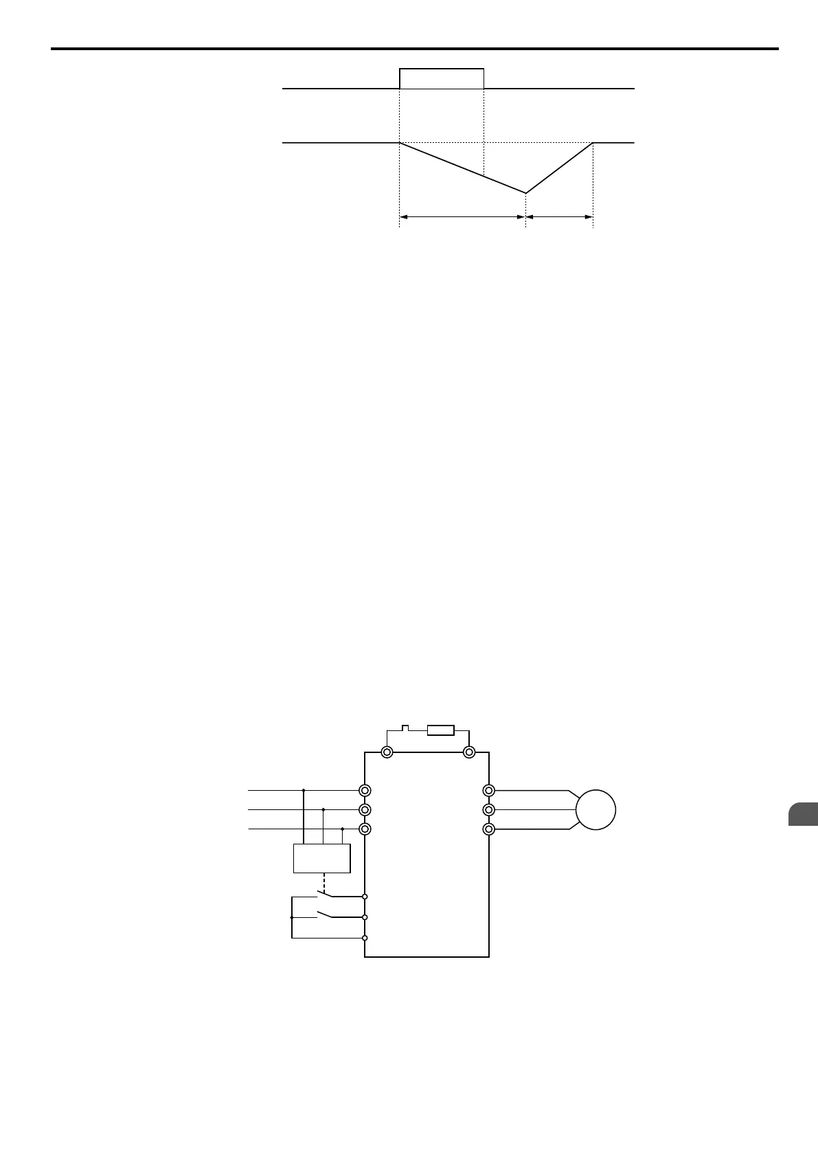
Output
frequency
OFF ON OFF
L2-06
L2-07
Figure 5.79 KEB Ride-Thru Timing Diagram for Multiple Drives
Note: If L2-06 is set to 0.0 s, C1-09 is used instead. If L2-07 is set to 0.0 s, the drive reaccelerates using the selected acceleration time.
Use this method with setting parameters L2-06 and L2-07 if multiple drives must decelerate but still keep the speed ratio
between the drives constant during power loss. In this case, a braking resistor is required in order to avoid overvoltage
trips.
KEB 2
In this mode the drive decelerates the motor by calculating the energy of the rotating system. The deceleration rate is
continuously adjusted so that the DC bus voltage meets the level set in parameter L2-11. The rotational energy is estimated
using the parameters L3-24 and L3-25. When the power supply returns, the drive accelerates back to the frequency reference
using the selected acceleration time.
Activation and Deactivation of the KEB Function
The KEB function requires parameter L2-01 to be set to 1 or 2 and a digital input has to be configured for the KEB 1 (H1-
oo = 65/66) or KEB 2 (H1-oo = 7A/7B) command. The input has to be enabled during KEB. Refer to Setting 65/66:
KEB Ride-Thru 1 (N.C.)/2 (N.O.) on page 184 and Refer to Setting 7A/7B: KEB Ride-Thru 2 (N.C./N.O.) on page
185 for details on setting the KEB input commands.
The KEB function is automatically activated when one of the conditions below becomes true.
• The DC bus voltage falls below the level set in parameter L2-05. The KEB input has to be set within 50 ms after the
KEB function was activated, or the drive will assume the power supply has returned and attempt to restart.
• The input programmed for KEB 1 or 2 is activated. This input should be triggered by an external undervoltage detection
relay.
The KEB function ends when one of the conditions below become true.
• The KEB input was released or
• The function was activated by DC bus voltage detection and no KEB input was set within 50 ms after the KEB activation.
Figure 5.80 shows a wiring example for triggering the KEB function at power loss using digital input S6.
M
R/L1
S/L2
T/L3
U/T1
V/T2
W/T3
B1 B2
L1
L2
L3
Braking
Resistor
UV Detection
Relay
S6 - KEB command 1 or 2
S1 - Start command
SC
Figure 5.80 KEB Function Wiring Example
Note: Make sure the Run command is not switched off when momentary power loss occurs. If the Run command is shut off, the drive will
not accelerate back to speed when the power is restored.
KEB Related Adjustment Parameters
The KEB 1 functions can be adjusted using the following parameters:
•
L2-05, Undervoltage Detection Level
5.8 L: Protection Functions
YASKAWA ELECTRIC SIEP C710606 16C YASKAWA AC Drive – V1000 Technical Manual
209
5
Parameter Details

 Loading...


