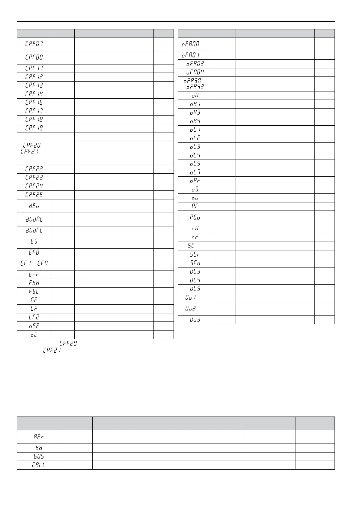
LED Operator Display Name Pg.
CPF07
Terminal Board Communication
Fault
254
CPF08
EEPROM Serial Communications
Fault
254
CPF11 RAM Fault 254
CPF12 FLASH Memory Fault 254
CPF13 Watchdog Circuit Exception 254
CPF14 Control Circuit Fault 254
CPF16 Clock Fault 255
CPF17 Timing Fault 255
CPF18 Control Circuit Fault 255
CPF19 Control Circuit Fault 255
or
<1>
CPF20 or
CPF21
RAM Fault 255
FLASH Memory Fault 255
Watchdog Circuit Exception 255
Clock Fault 255
CPF22 A/D Conversion Error 255
CPF23 PWM Feedback Data Fault 255
CPF24 Drive Capacity Signal Fault 255
CPF25 Terminal Board Not Connected 255
dEv
Excessive Speed Deviation (for
Simple V/f with PG)
255
dWAL
DriveWorksEZ Program Error
Output
256
dWFL DriveWorksEZ Fault 256
E5
MECHATROLINK Watchdog
Timer Error
256
EF0 Option External Fault 268
to
EF1 to
EF7
External Fault (input terminal S1 to
S7)
256
Err EEPROM Write Error 257
FbH Excessive PID Feedback 257
FbL PID Feedback Loss 257
GF Ground Fault 257
LF Output Phase Loss 257
LF2 Current Imbalance 257
nSE Node Setup Error 258
oC Overcurrent 258
LED Operator Display Name Pg.
<3>
oFA00
Option Card Connection Error at
Option Port CN5-A
259
<3>
oFA01 Option Unit Fault 259
oFA03 Option Card Fault (Port A) 259
oFA04 Option Card Fault (Port A) 259
to
oFA30 to
oFA43
Option Card Fault (Port A) 259
oH Heatsink Overheat 259
oH1 Heatsink Overheat 259
oH3 Motor Overheat 1 (PTC input) 259
oH4 Motor Overheat 2 (PTC input) 260
oL1 Motor Overload 260
oL2 Drive Overload 261
oL3 Overtorque Detection 1 261
oL4 Overtorque Detection 2 261
oL5 Mechanical Weakening Detection 1 261
oL7 High Slip Braking oL 261
oPr Operator Connection Fault 262
oS Overspeed (for Simple V/f with PG) 262
ov Overvoltage 262
PF Input Phase Loss 263
PGo
PG Disconnect (for Simple V/f with
PG)
263
rH Dynamic Braking Resistor 263
rr Dynamic Braking Transistor 263
<2>
SC IGBT Short Circuit 264
SEr Too Many Speed Search Restarts 264
STo Pull-Out Detection 264
UL3 Undertorque Detection 1 264
UL4 Undertorque Detection 2 264
UL5 Mechanical Weakening Detection 2 264
<3>
Uv1 Undervoltage 265
<3>
Uv2
Control Power Supply
Undervoltage
265
Uv3 Soft Charge Circuit Fault 265
<1>
Displayed as when occurring at drive power up. When one of the faults occurs after successfully starting the drive, the display will
show .
<2> Available in drive software versions PRG: 1020 and later.
<3> Uv1 and Uv2 faults are not saved to the fault history
n
Minor Faults and Alarms
When a minor fault or alarm
occurs, the ALM LED flashes and the text display shows an alarm code. A fault has occurred
if the text remains lit and does not flash. Refer to Alarm Detection on page 266. An overvoltage situation, for example,
can trigger both faults and minor faults. It is therefore important to note whether the LEDs remain lit or if the LEDs flash.
Table 6.6 Minor Fault and Alarm Displays
LED Operator Display Name
Minor Fault Output
(H2-oo = 10)
Pg.
AEr
Station Address Setting Error (CC-Link, CANopen,
MECHATROLINK)
YES 266
bb Drive Baseblock No output 266
bUS Option Card Communications Error YES 266
CALL Serial Communication Transmission Error YES 266
6.3 Drive Alarms, Faults, and Errors
250
YASKAWA ELECTRIC SIEP C710606 16C YASKAWA AC Drive – V1000 Technical Manual

 Loading...


