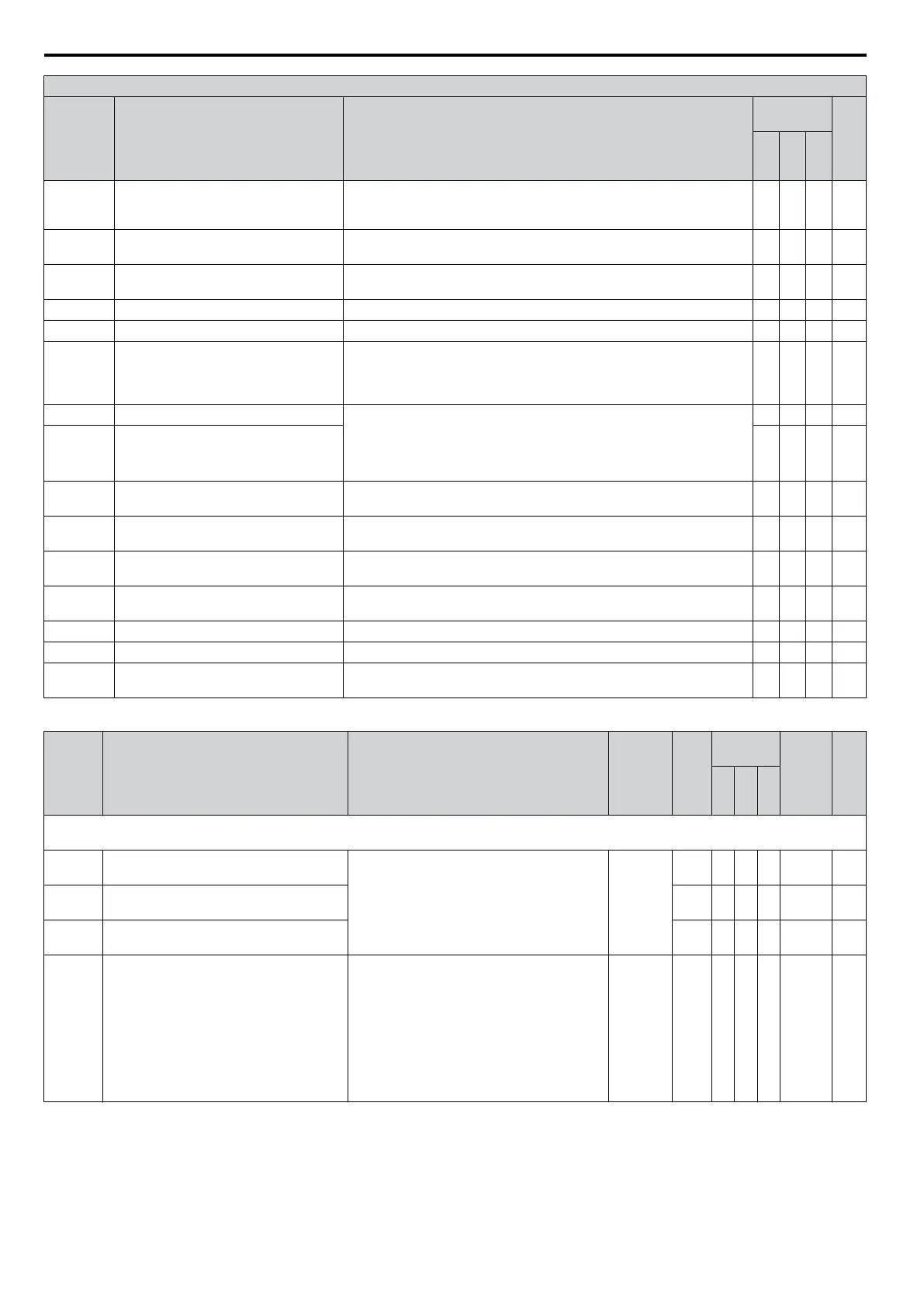
H1 Multi-Function Digital Input Selections
H1-oo
Setting
Function Description
Control
Mode
Pg.
V/
f
O
L
V
P
M
62 External Search Command 2
Closed: Activates Current Detection Speed Search from the frequency
reference b3-01 = 0. Activates Speed Estimation Type Speed search if
b3-01 = 0.
O O O 184
65 KEB Ride-Thru 1 (N.C.)
Open: KEB Ride-Thru 1 enabled
Closed: Normal operation
O O O 184
66 KEB Ride-Thru 1 (N.O.)
Open: Normal operation
Closed: KEB Ride-Thru 1 enabled
O O O 184
67 Communications Test Mode Tests the MEMOBUS/Modbus RS-485/422 interface. O O O 184
68 High-Slip Braking Closed: High-Slip braking is executed. Drive stops. O - - 184
6A Drive Enable
Open: Drive disabled.
If this input is opened during run, then the drive will stop as specified by
parameter b1-03.
Closed: Ready for operation.
O O O 184
75 Up 2 Command Open: Maintains the current frequency reference.
Closed: Increases or decreases the frequency reference.
UP 2 and Down 2 commands must be set in combination with each other.
The frequency reference source must be assigned to the operator (b1-01
= “0”).
O O O 184
76 Down 2 Command O O O 184
7A KEB Ride-Thru 2 (N.C.)
Open: KEB Ride-Thru 2 enabled
Closed: Normal operation
O O O 185
7B KEB Ride-Thru 2 (N.O.)
Open: Normal operation
Closed: KEB Ride-Thru 2 enabled
O O O 185
7C Short-Circuit Braking (N.O.)
Open: Normal operation
Closed: Short-Circuit Braking
- - O 185
7D Short-Circuit Braking (N.C.)
Open: Short-Circuit Braking
Closed: Normal operation
- - O 185
7E Forward/Reverse Detection Direction of rotation detection (for V/f with Simple PG Feedback) O - - 186
90 to 96 DWEZ Digital Inputs 1 to 7 Reserved for DWEZ input functions O O O 186
9F DriveWorksEZ enable
Open: DWEZ enabled
Closed: DWEZ disabled
O O O 186
<1> Available in drive software versions PRG: 1016 and later.
No. Name Description Range Def.
Control
Mode
Addr.
Hex
Pg.
V/
f
O
L
V
P
M
H2: Multi-Function Digital Outputs
Use H2 parameters to assign functions to the multi-function digital outputs.
H2-01
Terminal MA, MB and MC Function
Selection (relay)
Refer to H2 Multi-Function Digital Output
Settings on page 353 for a description of
setting values.
0 to 192
<1>
E A A A 40B 186
H2-02
Terminal P1 Function Selection (open-
collector)
0 A A A 40C 186
H2-03
Terminal P2 Function Selection (open-
collector)
2 A A A 40D 186
H2-06 Watt Hour Output Unit Selection
Sets the output units for the watt hours when
Watt Hour Pulse Output is selected as the
digital
output (H2-01, H2-02, or H2-03 = 39).
Outputs a 200 ms pulse signal when the watt-
hour counter increases by the units selected.
0: 0.1 kWh units
1: 1 kWh units
2: 10 kWh units
3: 100 kWh units
4: 1000 kWh units
0 to 4 0 A A A 437 195
<1> The availability of certain functions depends on the control method used.
B.2 Parameter Table
352
YASKAWA ELECTRIC SIEP C710606 16C YASKAWA AC Drive – V1000 Technical Manual

 Loading...


