Total Access 5000 Business Services Deployment Guide
2-28 65K510DEP08-1A
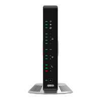
NetVanta 873 Description
TheNetVanta873DS3EFMisa MEFcompliant,EFMbondedNTUdesignedforcost‐effective
deploymentofdataservicestosmallandmediumsizebusinessessupportinguptothree
DS3s.TheNetVan ta873acceptsunchannelizedDS3sanddelivers10/100Base‐TEthernet,as
wellasaGigabitEthernetSFPportfor
customerLANextension.TheDS3sareterminatedin
BNCconnectorsandoperateatthestandard44.736Mbpsdatarate.TheNetVanta873
providesanaggregatedatarateupto134.208MbpsoverasingleEFMbondinggroup.
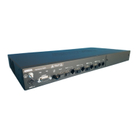
NetVanta 8044 Description
TheNetVanta8044BusinessServices(NTE)isaGigabit‐EthernetNTEorEthernetAccess
Device(EAD)thatsupportspointtopointdeploymentforGigabit‐Ethernetservicesfromthe
TotalAccess5000platformoranyotherEthernet‐serviceplatformthatsupportsstandard‐
basedEthernetoverFiber(EoF)implementations.TheADTRANEoFsolution
isaMEF
compliantsolutionsupportingfamiliaroperationtoolsbasedonConnectivityFault
Management(CFM)andPe rformanceMonitoring(PM)EthernetOAMstandards,aswellas,
leadingauthenticationstandardssuchasRADIUSandTACACS+.
Installation Steps
TowallmountorrackmounttheNetVanta800,completethefollowingprocedure:
1. AttachmountingbracketstothesideoftheNetVanta800inthecorrectorientationfor
eitherrackmountorwallmountusingthetwoscrewsprovidedforeachbracket.
•Torackmounttheunit,usetheappropriaterack‐typescrewstomounttheNetVanta
800intotherack.
•Towallmounttheunit,securetheNetVanta800tothewallwithappropriatescrews.
2. Connecttheframegroundfromtheframegroundlugontheupperrightrearpanelof
theNetVanta800totheequipmentrackgroundingscreworotherappropriate
groundingconnection.
3. Makepowerconnectionsto
theNetVanta800.
•Areadilyaccessibledisconnectdevice,suchasarackmountfuseandalarm
panelthatissuitablyapprovedand rated,shouldbeincorporatedinto the
fixedwiring
•C onnecttoareliablygrounded ±48VD Cor±24VDC source thatis
electricallyisolatedfromtheACsource
•The branchcircuitovercurrentprotection
shouldbeaslow‐blowfuseor
circuitbreaker
a. DeterminewhichfusepairsaretosupplypowertotheNetVanta800.
b. RemovethefusesfromtheAandBslotsforthepair.
c. Connect RET A,PWR A,RET B,andPWR B tothepowerconnector.PWR refersto
respective±48VDCor±24VDCpowersources;RET referstorespectivereturns.
4. Apply
powerandcheckvoltages.
 Loading...