Rockwell Automation Publication 193-UM015E-EN-P - October 2015 143
System Operation and Configuration Chapter 4
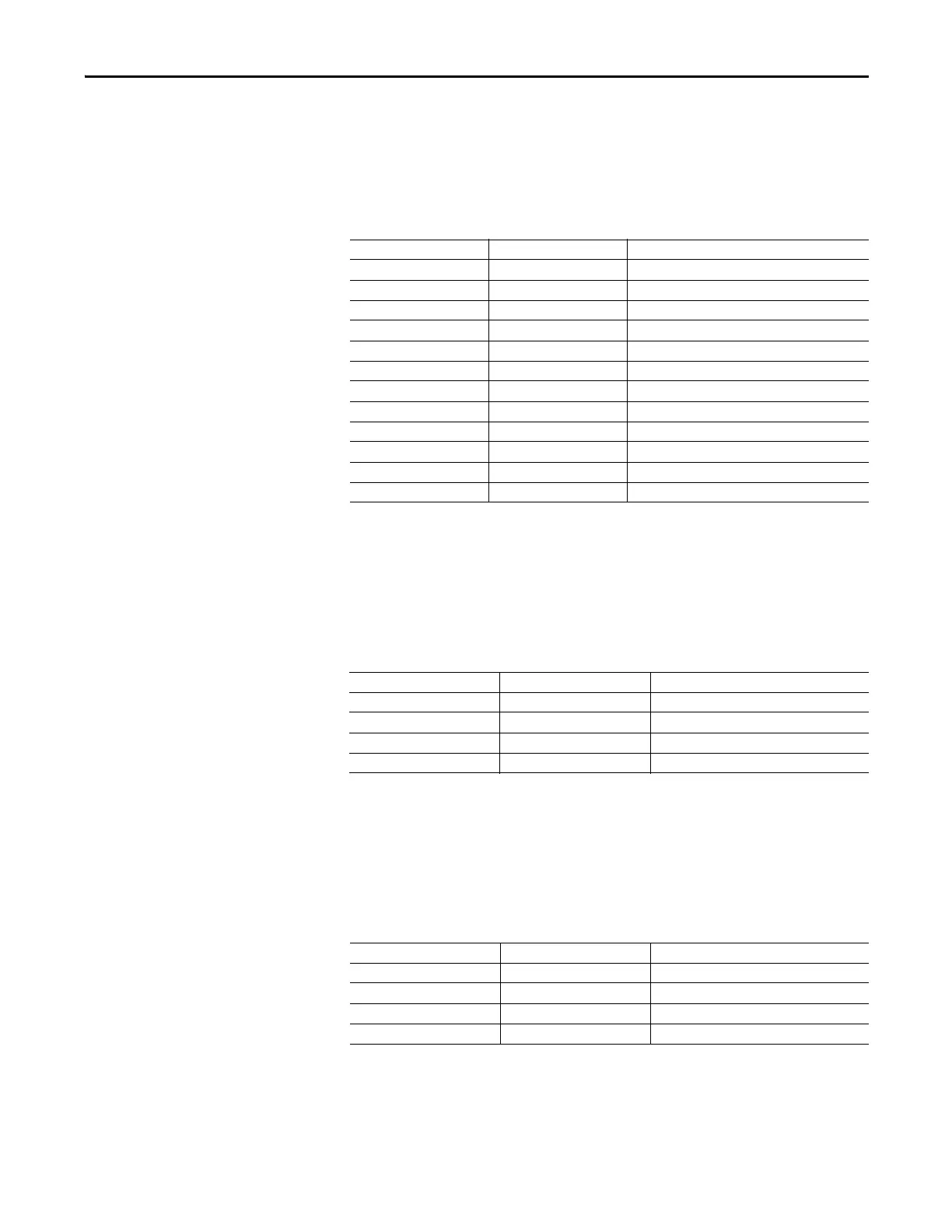
Analog Module 3 – Output Channel 00 Selection
Analog Module 3 – Output Channel 00 Selection (Parameter 527) defines the
E300 relay parameter that Output Channel 00 represents.
Table 193 - Analog Module 3 – Output Channel 00 Selection (Parameter 527)
Analog Module 3 – Output Channel 00 Expansion Bus Fault Action
Analog Module 3 – Output Channel 00 Expansion Bus Fault Action (Parameter
528) defines the value that the E300 Analog I/O Expansion Module Output
Channel 00 provides when there is an E300 Expansion Bus fault.
Table 194 - Analog Module 3 – Output Channel 00 Expansion Bus Fault Action (Parameter 528)
Analog Module 3 – Output Channel 00 Protection Fault Action
Analog Module 3 – Output Channel 00 Expansion Bus Fault Action (Parameter
529) defines the value that the E300 Analog I/O Expansion Module Output
Channel 00 provides when the E300 is in a tripped state.
Table 195 - Analog Module 3 – Output Channel 00 Protection Fault Action (Parameter 529)
Value Assignment Description
0 AveragePCTFLA Average %FLA (0…100%)
1 ScaledAvgPctFLA Scaled Average %FLA (0…200%)
2 PercentTCU %TCU (0…100%)
3 GFCurrent Ground Fault Current (Ground Fault Type Range)
4 CurrentImbalance Current Imbalance (0…100%)
5 AvgLLVoltage Average L-L Voltage (0…PT Primary)
6 VoltLLImbalance
Voltage Imbalance (0 …100%)
7 TotalkW Total kW (0…FLA x PT Primary x 1.732)
8 TotalkVA Total kVA (0…FLA x PT Primary x 1.732)
9 Total kVAR Total kVAR (0…FLA x PT Primary x 1.732)
10 TotalPF Total Power Factor (-50% Lagging…+50% Leading)
11 UserDLXData User-defined Value (-32768 …+32767)
Value Assignment Description
0 Zero Provide an analog signal of zero
1 Maximum Provide an analog signal equal to the high limit
2 Minimum Provide an analog signal equal to the low limit
3 HoldLastState Provide the last known analog signal
Value Assignment Description
0 Ignore Continue providing the appropriate analog signal
1 Maximum Provide an analog signal equal to the high limit
2 Minimum Provide an analog signal equal to the low limit
3 HoldLastState Provide the analog signal at the time of the fault

 Loading...


