Rockwell Automation Publication 193-UM015E-EN-P - October 2015 159
Operating Modes Chapter 5
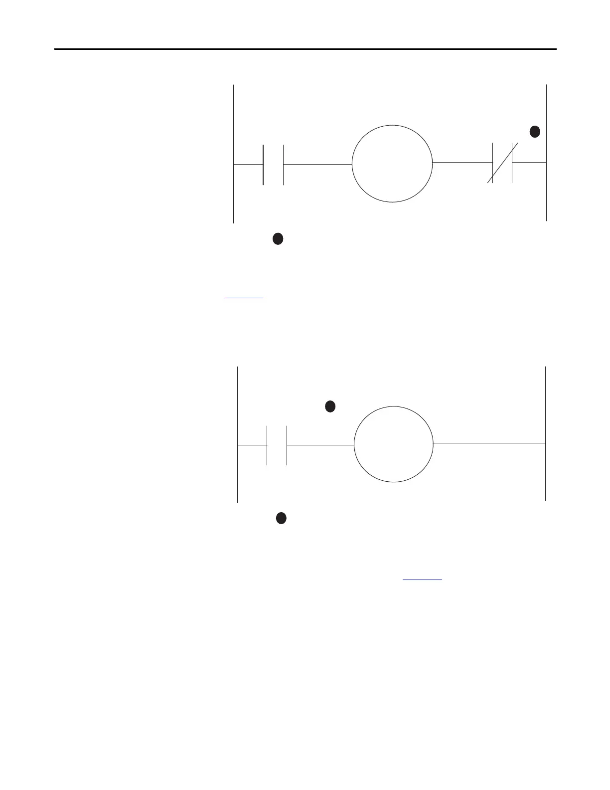
Figure 59 - Trip Relay Wiring Diagram
The E300 relay can also be wired as a control relay so that the relay that is
controlled by the communication network opens when a trip event occurs.
Figure 60
is a wiring diagram of a non-reversing starter with Relay 0 configured as
a control relay. Relay 0 receives control commands from an automation controller
to energize or de-energize the contactor coil. Relay 0 also goes to an open state
when there is a trip event.
Figure 60 - Control Relay Wiring Diagram
DeviceLogix Program
The DeviceLogix program that is shown in Figure 61 is automatically loaded and
enabled in the E300 on power-up or when Operating Mode (Parameter 195) is
set to a value of 26.
Relay 1
Relay 0
Configured as a
Trip Relay
R13 R14
A1
A2
M
R03
R04
1
1
Contact shown with supply voltage applied.
Relay 0
Configured as a
Control Relay
R03 R04
A1
A2
M
1
1
Contact shown with supply voltage applied.

 Loading...


