168 Rockwell Automation Publication 193-UM015E-EN-P - October 2015
Chapter 5 Operating Modes
2. Output Pt00 Assignment (Parameters 202) must be set to Control Relay.
3. Overload Trip must be enabled in TripEnableI (Parameter 183).
4. Feedback Timeout Trip in TripEnableC (Parameter 186) or Feedback
Time
out Warning in WarningEnableC (Parameter 192) must be enabled.
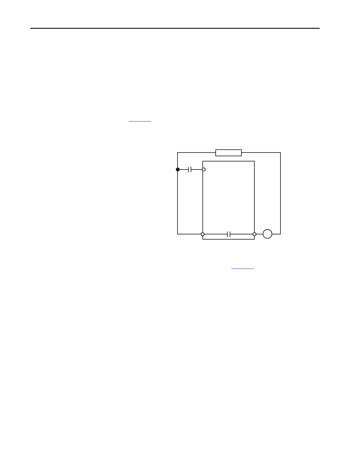
Wiring Diagram
The E300 relay’s Output Relay 0 is wired as a control relay in which the relay is
controlled by the communication network and opens when a trip event occurs.
Figure 73
is a wiring diagram of a non-reversing starter with the contactor
auxiliary wired to Input 0 and Output Relay 0 configured as a control relay.
Figure 73 - Non-reversing Starter (Network) with Feedback Wiring Diagram
DeviceLogix Program
The DeviceLogix program that is shown in Figure 74is automatically loaded and
enabled in the E300 on power-up or when Operating Mode (Parameter 195) is
set to a value of 4.
R03 R04
Relay 0
Run
E300
Control Power
Run Aux
IN 0

 Loading...


