Rockwell Automation Publication 193-UM015E-EN-P - October 2015 215
Operating Modes Chapter 5
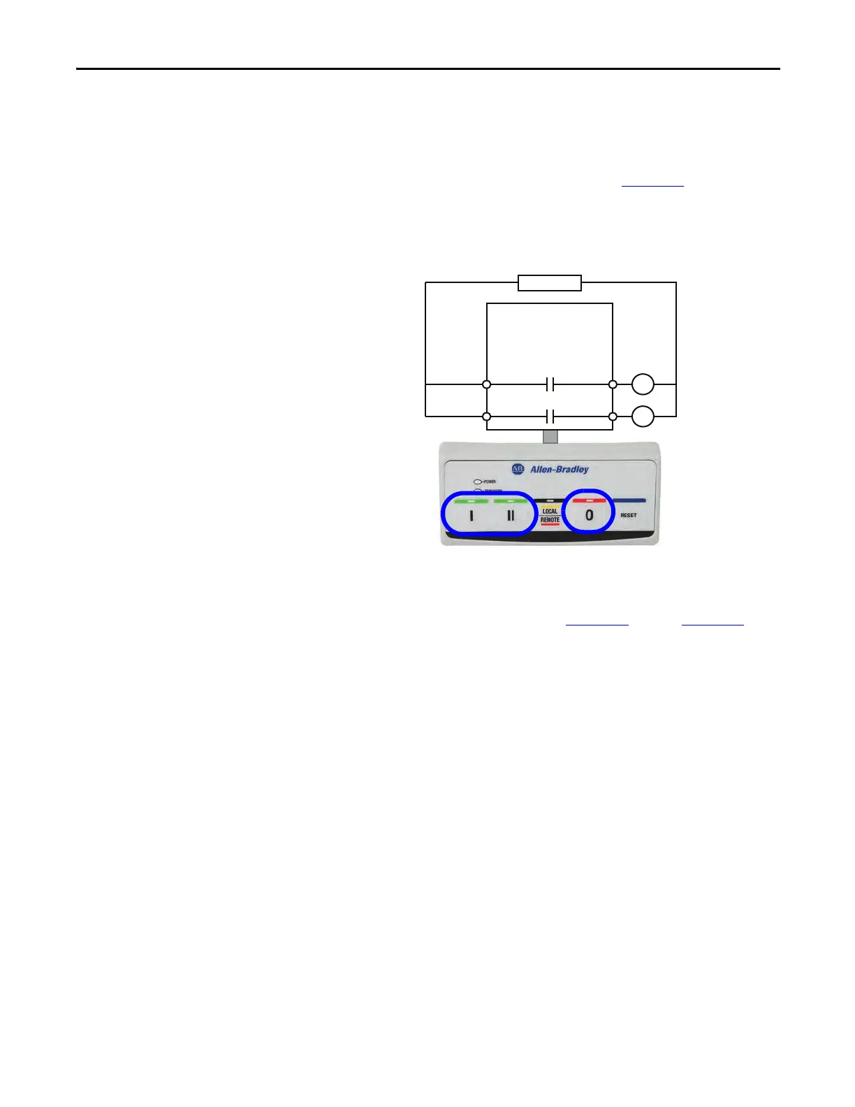
Wiring Diagram
The E300 relay’s Output Relay 0 is wired as a control relay to the forward
contactor, and Output Relay 1 is wired as a control relay to the reversing
contactor. Both relays open when a trip event occurs. Figure 120
is a wiring
diagram of a reversing starter with Output Relay 0 and Output Relay 1
configured as control relays.
Figure 120 - Reversing Starter (Operator Station) Wiring Diagram
DeviceLogix Program
The DeviceLogix program that is shown in Figure 121 through Figure 124 is
automatically loaded and enabled in the E300 on power-up or when Operating
Mode (Parameter 195) is set to a value of 29.
R13 R14
Relay 1
Run Reverse
E300
Control Power
I- Run Forward
0- Stop
II- Run Reverse
R03 R04
Relay 0
Run Forward

 Loading...


