Rockwell Automation Publication 193-UM015E-EN-P - October 2015 227
Operating Modes Chapter 5
Rules
1. Available for Control Module firmware v5.000 and higher.
2. Output Pt00 Assignment (Parameters 202) must be set to Control Relay.
3. Output Pt01 Assignment (Parameters 203) must be set to Control Relay.
4. Overload Trip must be enabled in TripEnableI (Parameter 183).
5. Communication Fault & Idle Override (Parameter 346) must be enabled.
6. Network Fault Override (Parameter 347) must be enabled.
Wiring Diagram
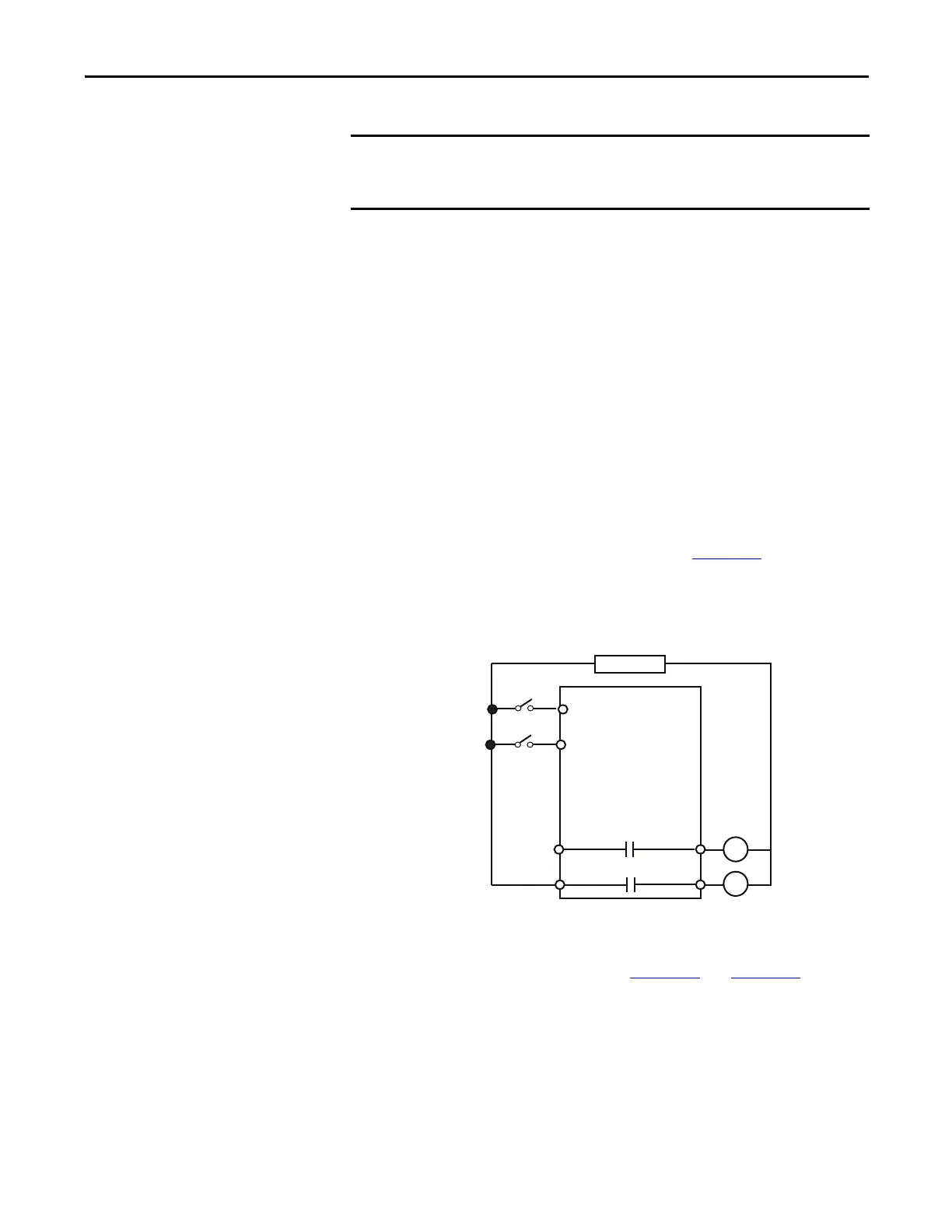
The E300 relay’s Output Relay 0 is wired as a control relay to the forward
contactor and Output Relay 1 is wired as a control relay to the reversing
contactor. Both relays open when a trip event occurs. Figure 132
is a wiring
diagram of a reversing starter with Output Relay 0 and Output Relay 1
configured as control relays.
Figure 132 - Reversing Starter (Local I/O) – Two-wire Control Wiring Diagram
DeviceLogix Program
The DeviceLogix program that is shown in Figure 133 and Figure 134 is
automatically loaded and enabled in the E300 on power-up or when Operating
Mode (Parameter 195) is set to a value of 40.
The Reversing Starter (Local I/O) – Two-wire Control operating mode uses the
signal from Input 0 or Input 1 to control the starter. When an E300 powers up,
the starter energizes if either Input 0 or Input 1 is active.
R13 R14
Relay 0
Run Reverse
E300
IN 1
Run Reverse/Stop
Control Power
IN 0
R03 R04
Relay 0
Run Forward
Run Forward/Stop

 Loading...


