258 Rockwell Automation Publication 193-UM015E-EN-P - October 2015
Chapter 5 Operating Modes
Wiring Diagram
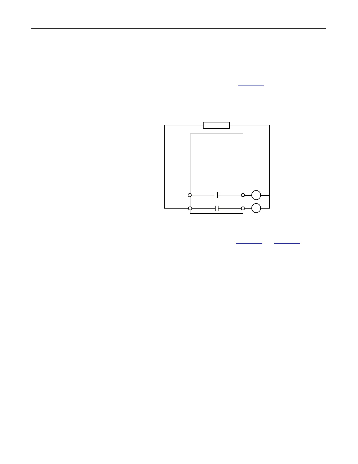
The E300 relay’s Output Relay 0 is wired as a control relay to the high-speed
contactor and Output Relay 1 is wired as a control relay to the low-speed
contactor. In this configuration, both relays are controlled by the communication
network and open when a trip event occurs. Figure 161
is a wiring diagram of a
two-speed starter with Output Relay 0 and Output Relay 1 configured as control
relays.
Figure 161 - Two-speed Starter (Network) Wiring Diagram
DeviceLogix Program
The DeviceLogix program that is shown in Figure 162 and Figure 163 is
automatically loaded and enabled in the E300 on power-up or when Operating
Mode (Parameter 195) is set to a value of 9.
R13 R14
Relay 0
Run Slow
E300
Control Power
R03 R04
Relay 0
Run Fast

 Loading...


