Rockwell Automation Publication 193-UM015E-EN-P - October 2015 267
Operating Modes Chapter 5
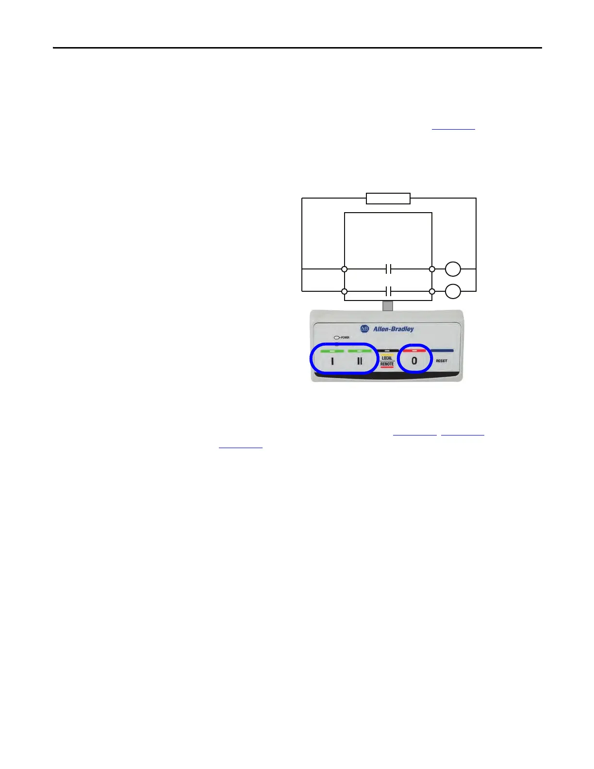
Wiring Diagram
The E300 relay’s Output Relay 0 is wired as a control relay to the high-speed
contactor, and Output Relay 1 is wired as a control relay to the low-speed
contactor. Both relays open when a trip event occurs. Figure 170
is a wiring
diagram of a two-speed starter with Output Relay 0 and Output Relay 1
configured as control relays.
Figure 170 - Two-speed Starter (Operator Station) Wiring Diagram
DeviceLogix Program
The DeviceLogix program that is shown in Figure 171, Figure 172, and
Figure 173
is automatically loaded and enabled in the E300 on power-up or when
Operating Mode (Parameter 195) is set to a value of 33.
R13 R14
Relay 1
Run Slow
E300
Control Power
I- Run Forward
0- Stop
II- Run Reverse
R03 R04
Relay 0
Run Fast

 Loading...


