604 Rockwell Automation Publication 193-UM015E-EN-P - October 2015
Chapter 10 EtherNet/IP Communication
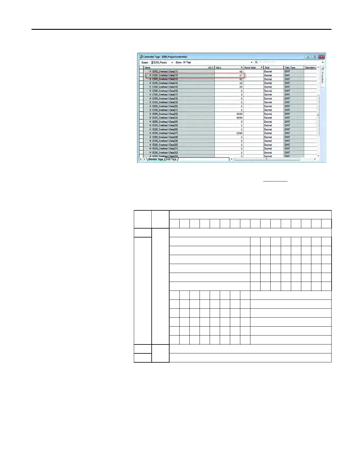
For example, E300_Overload:I.Data[12] represents L1 Current as shown below.
8. To control the output relays or remotely reset the E300 relay, navigate to
the output tags created by the Generic Profile. Table
566 represents the
Input Assembly data.
Table 566 - Instance 144 - Output (Consumed) Assembly
For example, E300_Overload:O.Data[0].0 represents Relay Output Pt00 as
shown below.
Bit
INT DINT1514131211109876543210
0
0
OutputStatus0
1
NetworkStart1 X
NetworkStart2 X
TripReset X
EmergencyStart X
RemoteTrip X
Reserved X X X
XHMILED1Green
XHMILED2Green
XHMILED3Green
X HMILED3Red
X HMILED4Red
X X X Reserved
2
1
DLXPtDeviceIn
3
DLXAnDeviceIn

 Loading...


