64 Rockwell Automation Publication 193-UM015E-EN-P - October 2015
Chapter 2 Installation and Wiring
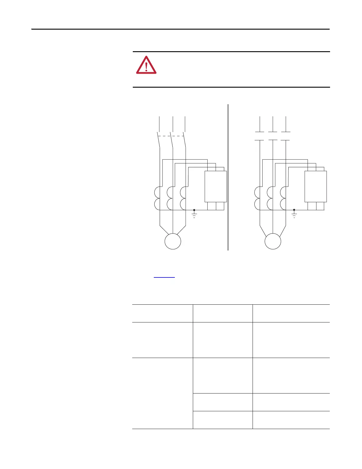
Figure 49 - External Current Transformer Connection
The E300 relay voltage-based sensing modules support a wide variety of power
systems. Tab le 22
lists the power systems supported by the specific sensing
module.
Table 22 - Supported Power Systems
ATTENTION: The improper selection of a current transformer can result in the
E300 relay reporting inaccurate motor operational data and possible motor
damage. The selected current transformer must be rated for protective relaying
applications.
NEMA
L1 L2
L3
L1/1 L2/3 L3/5
T1/2 T2/4 T3/6
M
T1
T2
T3
IEC
L1 L2
L3
K1
L1/1 L2/3 L3/5
T1/2 T2/4 T3/6
E300
M
Primary
Current
Transformers
Primary
Current
Transformers
E300
Catalog Number Connection Type Power System
193-ESM-VIG-__-__
592-ESM-VIG-__-__
Direct Single Phase
Delta
Wye
Grounded B Phase Delta
193-ESM-VIG-30A-CT Direct Single Phase
Delta
Wye
Grounded B Phase Delta
3 PT Delta
Wye
2 PT Single Phase
Open Delta

 Loading...


