Rockwell Automation Publication 193-UM015E-EN-P - October 2015 647
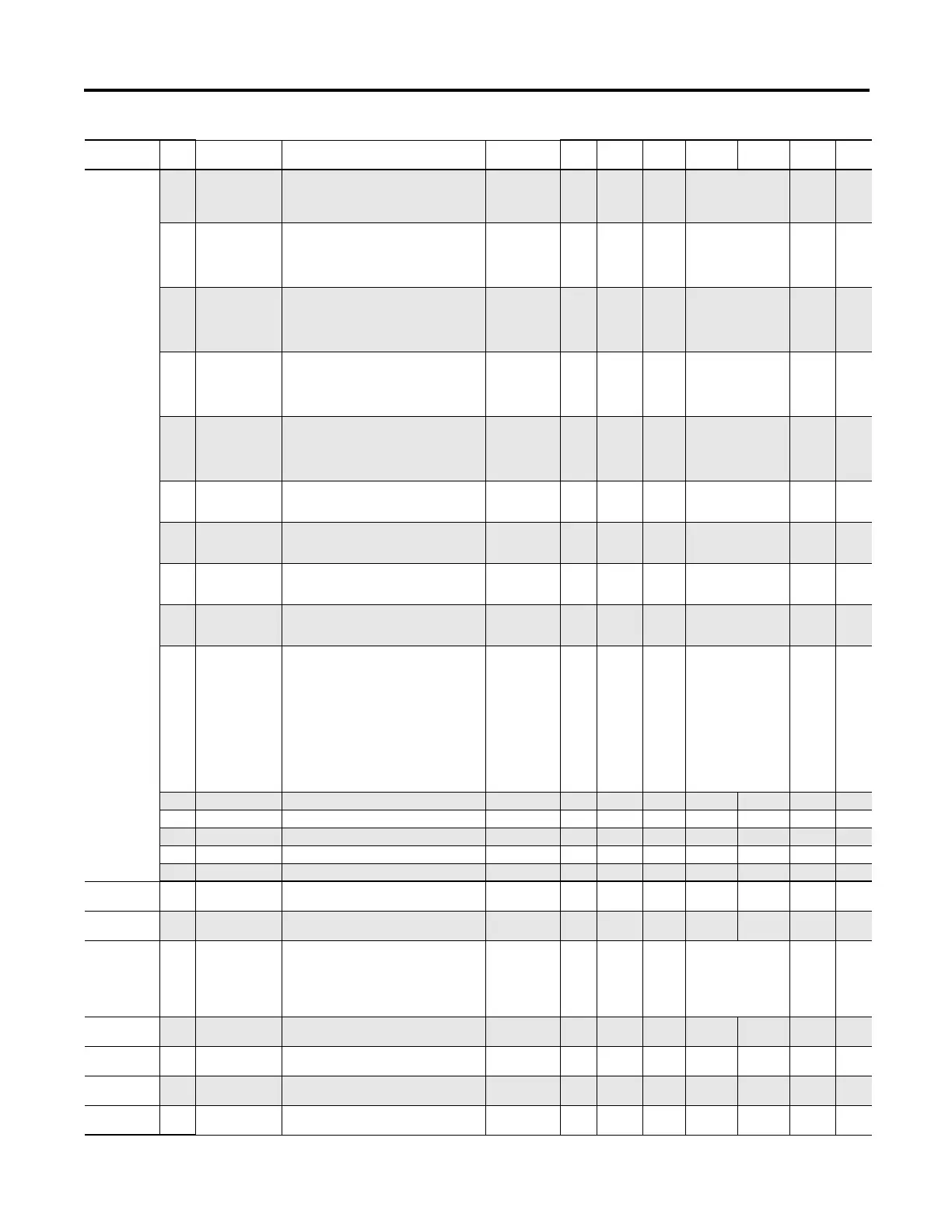
Parameter List Appendix B
Options Setup
(Continued)
224 OperStationType Select Operator
Station Type
USINT 1 1 0= IgnoreType
1= NoStation
2= ControlStation
3= DiagStation
0
225 DigitalMod1Type Select Digital I/O
Expansion Module
1 Type
USINT 1 1 0= IgnoreType
1=NoModule
2=4In2Out24VDC
3=4In2Out120VAC
4=4In2Out240VAC
0
226 DigitalMod2Type Select Digital I/O
Expansion Module
2 Type
USINT 1 1 0= IgnoreType
1=NoModule
2=4In2Out24VDC
3=4In2Out120VAC
4=4In2Out240VAC
0
227 DigitalMod3Type Select Digital I/O
Expansion Module
3 Type
USINT 1 1 0= IgnoreType
1=NoModule
2=4In2Out24VDC
3=4In2Out120VAC
4=4In2Out240VAC
0
228 DigitalMod4Type Select Digital I/O
Expansion Module
4 Type
USINT 1 1 0= IgnoreType
1=NoModule
2=4In2Out24VDC
3=4In2Out120VAC
4=4In2Out240VAC
0
229 AnalogMod1Type Select Analog I/O
Expansion Module
1 Type
USINT 1 1 0=IgnoreType
1=NoModule
2=3In1OutAnalog
0
230 AnalogMod2Type Select Analog I/O
Expansion Module
2 Type
USINT 1 1 0=IgnoreType
1=NoModule
2=3In1OutAnalog
0
231 AnalogMod3Type Select Analog I/O
Expansion Module
3 Type
USINT 1 1 0=IgnoreType
1=NoModule
2=3In1OutAnalog
0
232 AnalogMod4Type Select Analog I/O
Expansion Module
4 Type
USINT 1 1 0=IgnoreType
1=NoModule
2=3In1OutAnalog
0
233 MismatchAction Select Mismatched
Module Actions
0=warning 1=
fault
UINT 1 1 Bit0= ControlModule
Bit1= SensingModule
Bit2= CommsModule
Bit3= OperatorStation
Bit4= DigitalModule1
Bit5= DigitalModule2
Bit6= DigitalModule3
Bit7= DigitalModule4
Bit8= AnalogModule1
Bit9= AnalogModule1
Bit10= AnalogModule1
Bit11= AnalogModule1
0
234 Reserved
235 Reserved
236 Reserved
237 Reserved
238 Reserved
Current Setup 239 PLInhibitTime C.PhaseLossInhibitTime Phase Loss Inhibit
Time
USINT 1 1 0 250 0
Seconds
240 PLTripDelay C.PhaseLossTripDelay Phase Loss Trip
Delay
USINT 1 10 1 250 10
Seconds
241 GroundFaultType C.GroundFaultType Select Ground
Fault Type
USINT 1 1 0= Disabled
1= Internal1to5Amps
2= ExtPt02toPt1Amps
3= ExtPt1toPt5Amps
4= ExtPt5to1Amps
5= External1to5Amps
0
242 GFInhibitTime C.GroundFaultInhibitTime Ground Fault
Inhibit Time
USINT 1 1 0 250 10
Seconds
243 GFTripDelay C.GroundFaultTripDelay Ground Fault Trip
Delay
USINT 1 10 0 250 5
Seconds
244 GFTripLevel C.GroundFaultTripLimit Ground Fault Trip
Level
UINT 2 100 2 500 200 Amps
245 GFWarningDelay C.GroundFaultWarnDelay Ground Fault
Warning Delay
USINT 1 10 0 250 0
Seconds
Group
Param
No.
Parameter Name Device Profile Tag Name Description Type
Data Size
(bytes)
Scale
Factor
Min Max Default Units

 Loading...


