652 Rockwell Automation Publication 193-UM015E-EN-P - November 2013
Appendix B Parameter List
DeviceLogix Setup
(Continued)
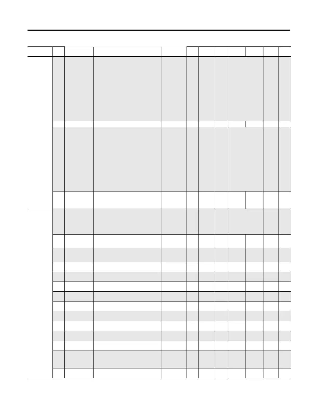
348 PtDeviceOuts Status of
DeviceLogix
Network Outputs.
UINT 2 1 Bit0= Pt00DeviceOut
Bit1= Pt01DeviceOut
Bit2= Pt02DeviceOut
Bit3= Pt03DeviceOut
Bit4= Pt04DeviceOut
Bit5= Pt05DeviceOut
Bit6= Pt06DeviceOut
Bit7= Pt07DeviceOut
Bit8= Pt08DeviceOut
Bit9= Pt09DeviceOut
Bit10= Pt10DeviceOut
Bit11= Pt11DeviceOut
Bit12= Pt12DeviceOut
Bit13= Pt13DeviceOut
Bit14= Pt14DeviceOut
Bit15= Pt15DeviceOut
0
349 Reserved
350 PtDevOutCOSMask When bit is set the
network output
will trigger a COS
message.
UINT 2 1 Bit0= Pt00DeviceOut
Bit1= Pt01DeviceOut
Bit2= Pt02DeviceOut
Bit3= Pt03DeviceOut
Bit4= Pt04DeviceOut
Bit5= Pt05DeviceOut
Bit6= Pt06DeviceOut
Bit7= Pt07DeviceOut
Bit8= Pt08DeviceOut
Bit9= Pt09DeviceOut
Bit10= Pt10DeviceOut
Bit11= Pt11DeviceOut
Bit12= Pt12DeviceOut
Bit13= Pt13DeviceOut
Bit14= Pt14DeviceOut
Bit15= Pt15DeviceOut
0
351 DLXUserDefData General Purpose
Data Value for Use
in DeviceLogix
Programs
UDINT 4 1 0 0xFFFFFFFF 0
Voltage Setup 352 VoltageMode C.VoltageMode Voltage Wiring
Mode
USINT 1 1 0= Delta
1= Wye
2= DeltaPTDelta2Wye
3= WyePTDelta2Wye
4= DeltaPTWye2Delta
5= WyePTWye2Delta
0
353 PTPrimary C.PTPrimary Potential
Tra nsf orm er
Primary Rating
UINT 2 1 1 65535 480
354 PTSecondary C.PTSecondary Potential
Tra nsf orm er
Secondary Rating
UINT 2 1 1 540 480
355 UVInhibitTime C.UnderVoltageInhibitTime Under Voltage
Inhibit Time
USINT 1 1 0 250 10
Seconds
356 UVTripDelay C.UnderVoltageTripDelay Under Voltage Trip
Delay
USINT 1 10 1 250 10
Seconds
357 UVTripLevel C.UnderVoltageTripLimit Under Voltage Trip
Level
UINT 2 10 0 65535 1000 Volt
358 UVWarningLevel C.UnderVoltageWarnLimit Under Voltage
Warning Level
UINT 2 10 0 65535 4000 Volt
359 OVInhibitTime C.OverVoltageInhibitTime Over Voltage
Inhibit Time
USINT 1 1 0 250 10
Seconds
360 OVTripDelay C.OverVoltageTripDelay Over Voltage Trip
Delay
USINT 1 10 1 250 10
Seconds
361 OVTripLevel C.OverVoltageTripLimit Over Voltage Trip
Level
UINT 2 10 0 65535 5000 Volt
362 OVWarningLevel C.OverVoltageWarnLimit Over Voltage
Warning Level
UINT 2 10 0 65535 4900 Volt
363 PhRotInhibitTime C.PhaseRotationInhibitTime Phase Rotation
Inhibit Time
USINT 1 1 0 250 10
Seconds
364 PhaseRotTripType C.PhaseRotationTripType_0
C.PhaseRotationTripType_1
Voltage Phase
Rotation Trip Type
USINT 1 1 1 0=
NoRotation
1= ABC
2= ACB
1
365 VIBInhibitTime C.VoltageImbalanceInhibitTime Voltage Imbalance
Inhibit Time
USINT 1 1 0 250 10
Seconds
Group
Param
No.
Parameter Name Device Profile Tag Name Description Type
Data Size
(bytes)
Scale
Factor
Min Max Default Units

 Loading...


