10. Card Cage
Image 10-40
5. Take a new SMPS unit and insert the board in the guides of the SMPS compartment. Pus h it completely
in.
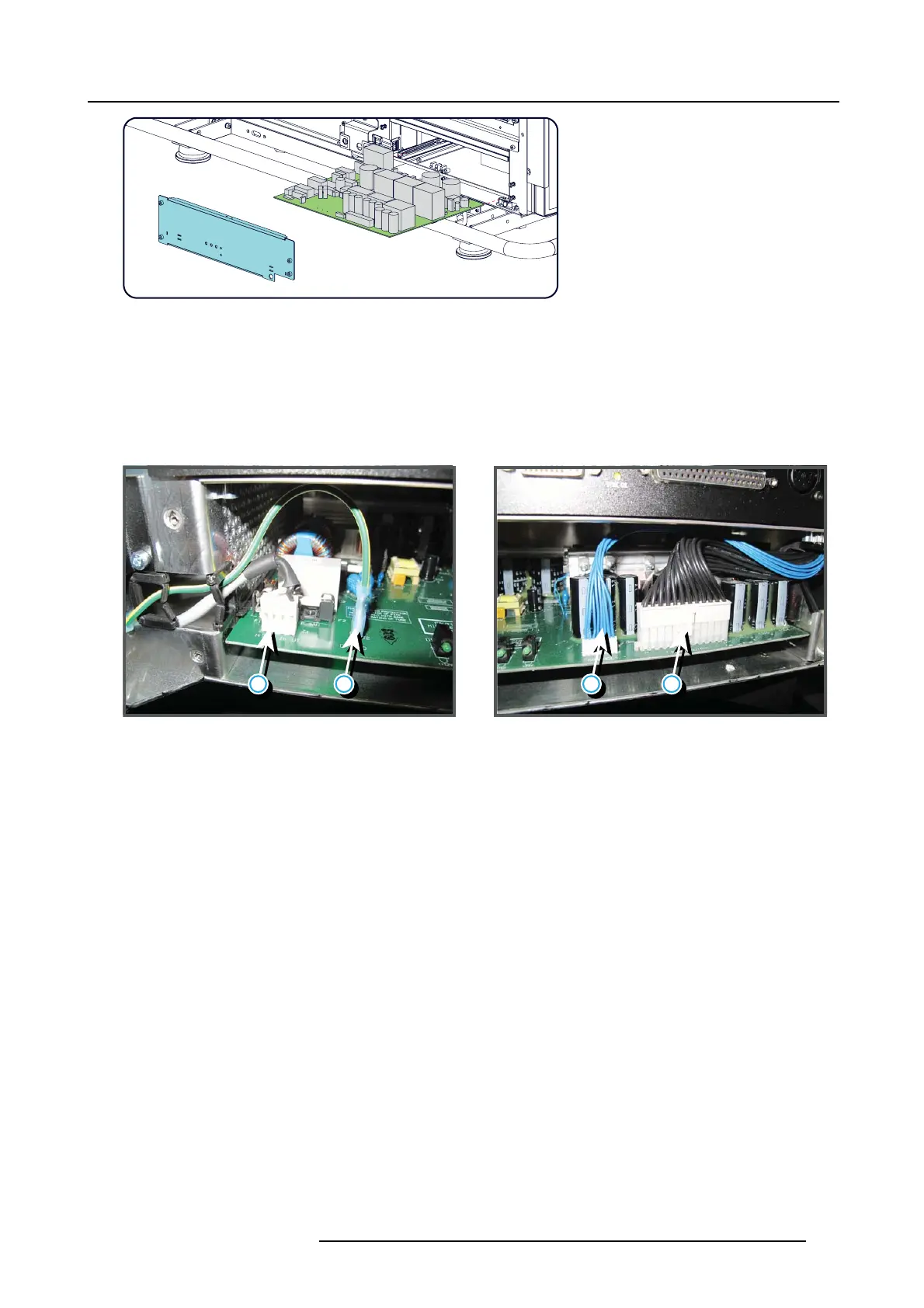
6. M ake the electrical connections:
- Mains input (reference 1)
- Groundwire(reference2)
- Control connector (blue wires) (reference 3)
- Power out connector (black wires) (reference 4)
Caution: Support the bottom of the SMPS board while plugging in the wire units.
1 2 3 4
Image 10-41
7. P lace the c over on its place and fasten the 4 retaining screws (reference 1 to 4 image 10-37).
R5905312 HDF W SERIES 24/01/2013
167

 Loading...


