14. Lenses and Lens Holder
14.10 Scheimpflug adjustment
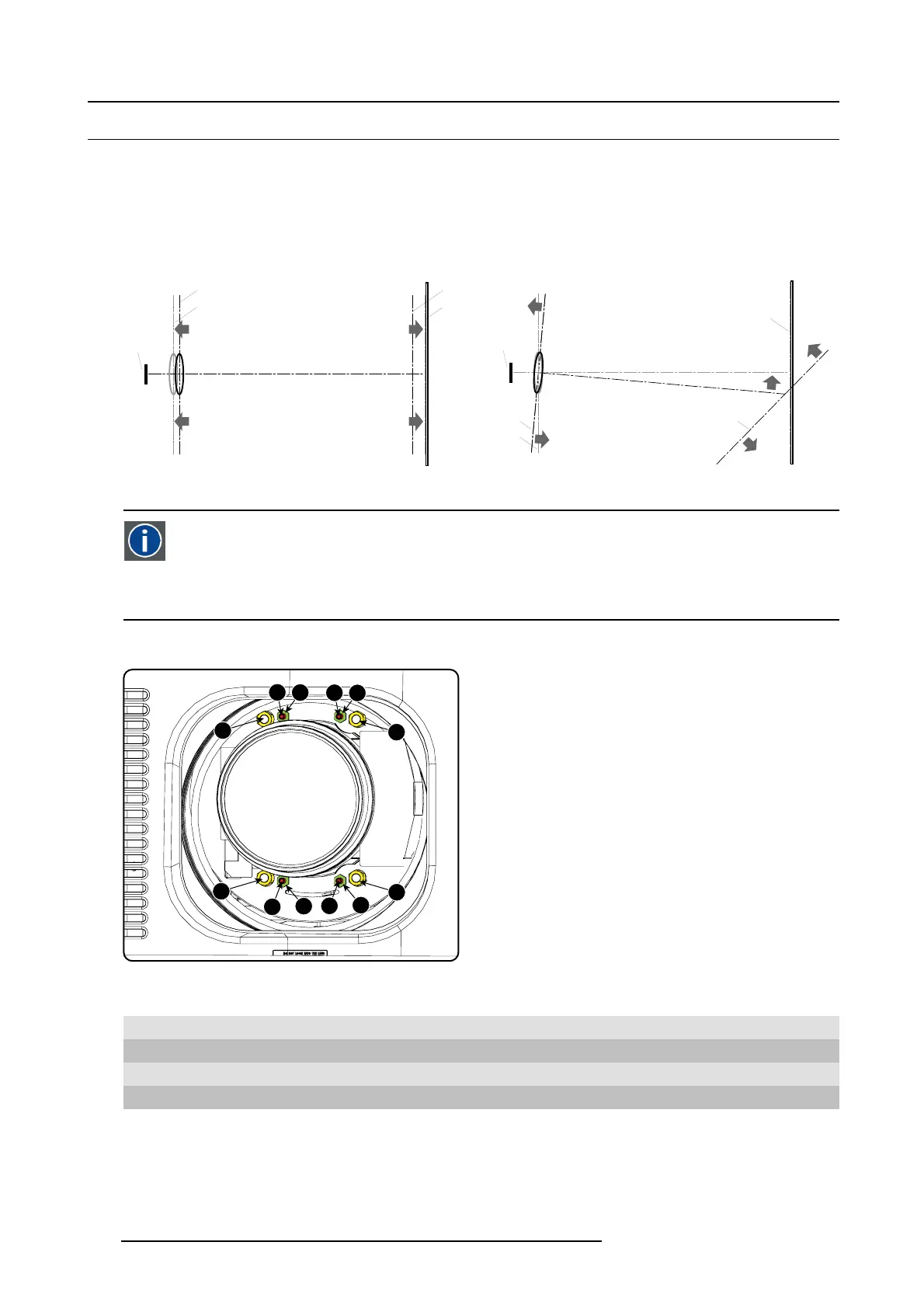
What has to be done ?
The lens holder has to be adjus ted s o that the “sharp focus plane” of the projected image falls together with the plane of the screen
(Fp1→Fp2). This is achieved by changing the distance between the DMD plane and the lens plane (Lp1→Lp2). The c loser the lens
plane comes to the DMD plane the further the sharp focus plane w ill be. It can sometimes happen that y ou won’t be able to get a
complete focused image on the screen due to a tilt (or swing) of the lens plane with respect to the DM D plane. This is also known
as Scheimpflug’s law. To solve this the lens plane must be placed parallel with the DMD plane. This can be achieve d by turning the
lens holder to remove the tilt (or swing) between lens plane and DMD plane (Lp3→Lp4).
SCREEN
DMD
Lp1
Lp2
Fp1
Fp2
SCREEN
DMD
Lp3
Lp4
Fp3
Fp4
(Scheimpflug)
Image 14-35
Scheimpflug principle
Scheimpflug principle
The "plane of sharp focus" can be changed so that any plane ca n be brought into sharp focus. When the D M D plane
and lens plane are parallel, the plane of sharp focus will als o be parallel to these t wo planes. If, however, the lens
plane is tilted with respect to the DMD plane, the plane of sharp focus will also be tilted according to geometrical and
optical properties. The DMD plane, the principal lens plane and the s harp focus plane will intersect in a line below the
projector for downward lens tilt.
Scheimpflug adjustment points
4
1
2
3
d
D
c
C
A
a
B
b
Image 14-36
Scheimpflug adjustments
Indication on drawing Function
4 Locking nut
1, 2 and 3
Scheimp flug adjustment nuts
A, B, C and D Set screws
a, b, c and d lock nuts
1, 2 and 3 are adjustment points.
4 is a locking point and NOT used during Scheimpflug adjustment.
230
R5905312 HDF W SERIES 24/01/2013

 Loading...


