19. Board Diagnostic LED’s
19.8 5 Cable Input board Diagnostic LEDs
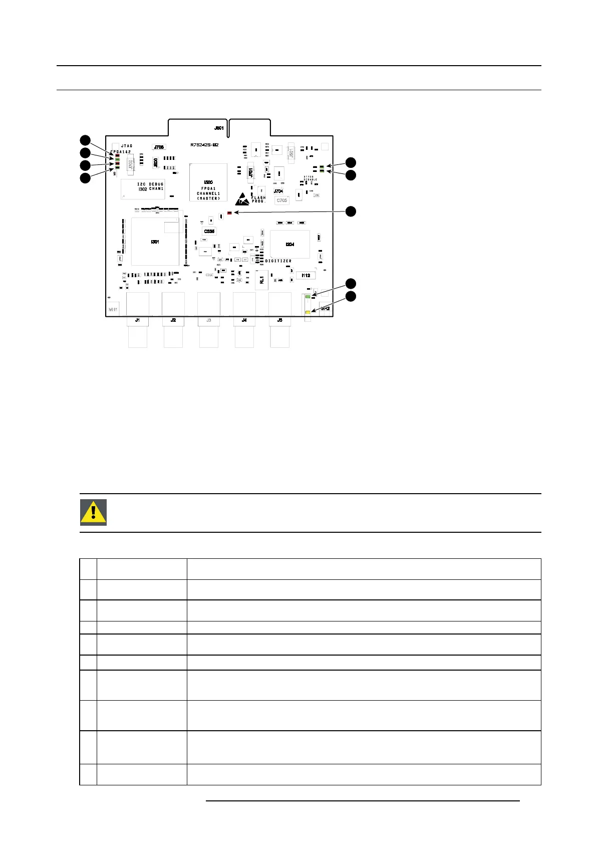
Location of the diagnostic LEDs
1
2
3
4
9
8
7
6
5
Image 19-10
1 INTERRUPT RE Q (red)
2 DCM CLOCK OK (green)
3 GP_LED3 (red)
4 CONV ADC SELECTED (green)
5 SYN C (yellow)
6 SEL (green)
7 FPGA CONFIG (red)
8 +5V OK (green)
9 +12V OK (green)
View on the diagnostic LEDs
The 5 Cable Input board is located inside the Input & Comm unication unit. Only the LE D s at the front side (cover plate) are visible
without opening the projector. To view the other diagnostic LEDs the In put & Commun ication unit has to be placed in the service
position as illustrated below (moved forward and tilted). The other LED s are then visible through the grid at the sides of the Input &
Communication unit.
CAUTION: Only operate the p
rojector for a few minutes while the Input & Communication unit is moved and
tilted in it’s service position. This to minimize the risk of exceeding the maximum permitted internal temper-
ature limit due to insufficient airfl ow.
Description of the diagnostic LEDs
Ref. Description (LED
color)
Comment
1
INTERRUPT REQ (red)
This LED lit up when an interrupt requirem ent arise.
2
DCM CLO CK OK
(green)
This LED lit up indicating that the output clock of the DCM is stable.
3
GP_LED3 (red) (not used, future e
xpansion).
4 CONV ADC
SELECTED (green)
There are two AD con vertors on the board, ADC9 8001 and ADV7802. This LED is to indicate
which AD convertor is used. This LED lit up incase the A DC is used and otherwise A DV is used.
5
SYNC (yellow). This LED lit up when a valid and s table input sync is detected for the applied source.
6
SEL (green). This LED it up when the 5 Cable input is selected. There are three data streams output from the 5
Cable board to the PMP board. Namely: ADC, ADV and test pattern. This LED lit up in case ADC
or ADV data is se lected to PMP. Otherwise internal test pattern is selected.
7
FPGA CONFIG (red). T his LED lit up du ring the start up of the 5 Cable Input and in case the FPGA of the 5 Cable Input is
not correct
ly loaded with the firmware. If this is the case try to reload the firmware and/or software
of the 5 Cable Input. If the problem remains replace the 5 Cable Input board.
8
+5V OK (green) This LE D lit up in normal condition and indicates that the +5V supply voltage from the Power
Backplane is available. The +5V is d erived from the +12V which is generated by the Power Box.
9
+12V OK (green) This LED lit up in normal condition an d indicates that the +12V supply voltage from the Pow er
Backplane is available. The +12V is generated on the Power Box.
R5905312 HDF W SERIES 24/01/2013 321

 Loading...


