10. Card Cage
10.1 Introduction HDF Input & Communication unit
HDF Input & Communication unit
The Input & Co mm unication unit is a c losed metal box which can easily be removed, as a drawer, from the projector chassis. At the
back side of the Input & Commu nication unit fits the PMP board w hich functions also as backplane for the input boards. The Warp
module and Deinterlacing m odule are mounted directly on the PM P board. At the upper front of the Input & C omm unication unit a re
the LCD display and Loc al K eypad located. Be hind the LCD display and Local keypad is the LCD display interface mounted.
The rear side of the Input & Communication unit contains 7 sockets. One socket for the control connection with the Power Backplane
and six sockets for the RGB data connections directly with the satellite formatter boards on the Light Processor unit.
CAUTION: The six sockets at the rear side of the Input & Communication unit are equipped with a latch to
capture the inserted plug. These latches are fragile. Always open the latch before pulling out the plug.
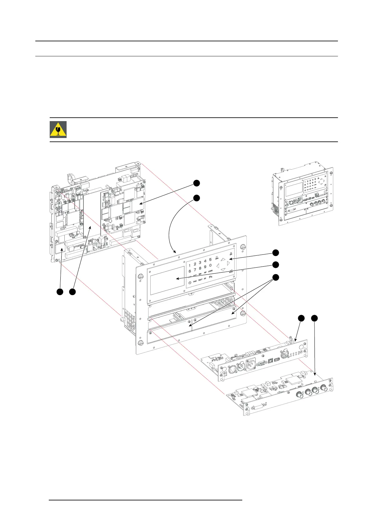
Parts of the Input & Communication unit
5
3
6
8 9
4
1 2
7
Image 10-1
1 PMP board.
2 Deinterlacing module.
3 Warp module.
4 LCD Display Interface.
5 Local Keypad.
6 LCD Display.
7 Unused input slots.
8 Communication m odule.
9 DVI/HDXDI input module.
Input & Communication unit exchange between projector families
The same Input & Communication unit is us ed in the HDX, HDF and HDQ families.
142
R5905312 HDF W SERIES 24/01/2013

 Loading...


