19. Board Diagnostic LED’s
19.1 Fan Control Board (FCB) Diagnostic LEDs
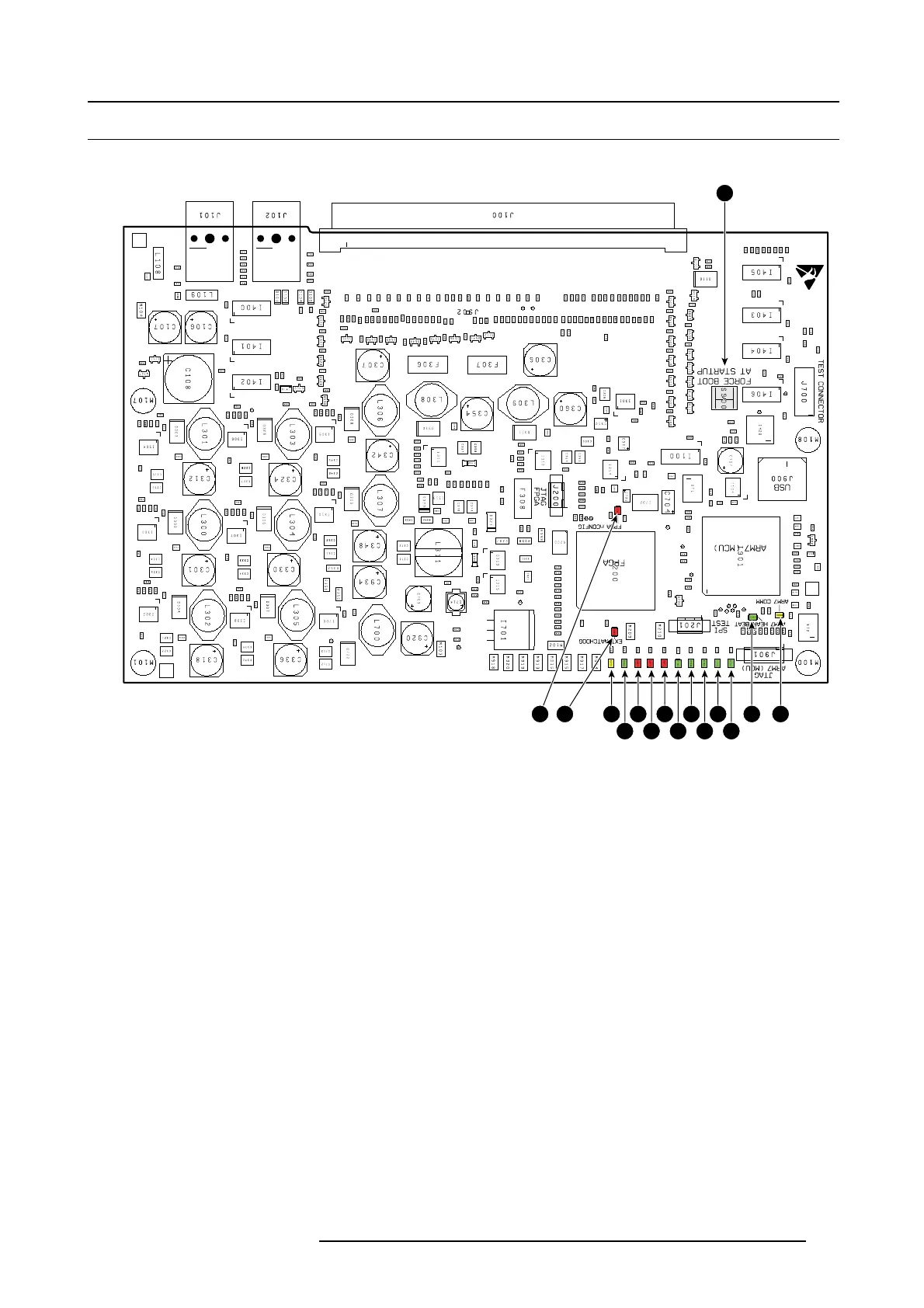
Location of the diagnostic LEDs
10
9
8
7
6
5
4
3
2 131112 14
1
15
Image 19-1
1 +1.5V OK (green)
2 +14V OK (green)
3 +5V OK (green)
4 +24V OK (green)
5 +3.3V OK (green)
6 OVERTEMP (red)
7 LPS ERROR (red)
8 UNDERTEMP (red)
9 FPGA HEARTBEAT (green)
10 LPS COMM (yellow)
11 EXT WAT CHDOG (red)
12 FPGA CONFIG (red)
13 FCB HEARTBEAT (green)
14 FCB COMM (yellow)
15 S WITCH FORCE BOOT
View on the diagnostic LEDs
The Fan Control B oard is located behind the Input & Communication unit. To view the diagnostic LEDs of the Fa n Control Board the
Input & Communication unit has to be placed in the service position as illustrated below (moved forward and tilted).
R5905312 HDF W SERIES 24/01/2013
307

 Loading...


