19. Board Diagnostic LED’s
19.7 Pixel Mapping Processor Diagnostic LEDs
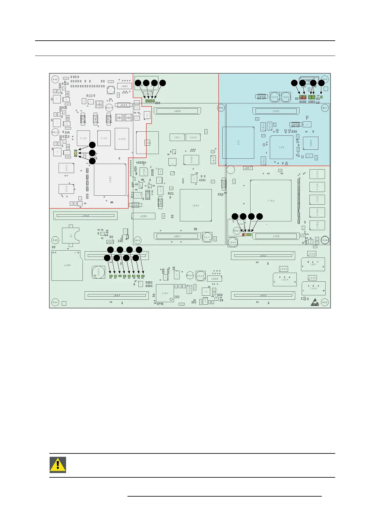
Location of the diagnostic LEDs
PMP
FIBµC
1
4 5 6 7
20 21 22 23
12
13
14
15
16
17
18
19
8 9 11
2
3
10
Image 19-9
1 (not used, future expansion).
2 IR RECEIVED (green).
3 IR ACKNOWLEDGED (green).
4 SYNC INPUT1 (green).
5 SYNC INPUT2 (green).
6 SYNC INPUT3 (green).
7 SYNC INPUT4 + HEA RTBEAT (green).
8 FIB FPGA CONF IG (red/yellow/green).
9 POWERGOOD STATUS (red/yellow:green).
10 (not used, future expansion).
11 RESET FPGA DONE (green).
12 ++12V OK (green).
13 LOCAL STBY OK (green).
14 PMP HEARTBEAT (green).
15 +12V OK (green).
16 LOCAL POWE R OK (green).
17 INPUT FPGA CONFIG (green).
18 SCALER FPGA CONFIG (green).
19 FIBFPGACONFIG(green).
20 SCALER H EARTBEAT (re d)
21 SCALER SYSTEM RESET (yellow)
22 SCALER MEMORY R EADY (green)
23 SCALER HEARTBEAT (green)
View on the diagnostic LEDs
The Pixel Mapping Processor is located inside the Input & Com munication unit. None of the LEDs are visible without op ening the
projector. To view the diagnostic LEDs the Input & Communication unit has to be placed in the service position as illustrated below
(moved forward and tilted). The LEDs are t hen visible through the grid at the sides of the Input & Co mm unication unit.
CAUTION: Only operate the projector for a few minutes while the Input & Communication unit is moved and
tilted in it’s service position. This to minimize the risk of exceeding the maximum permitted internal temper-
ature limit due to insufficient airfl ow.
R5905312 HDF W SERIES 24/01/2013 319

 Loading...


