12. Start Pulse Generator
Image 12-8
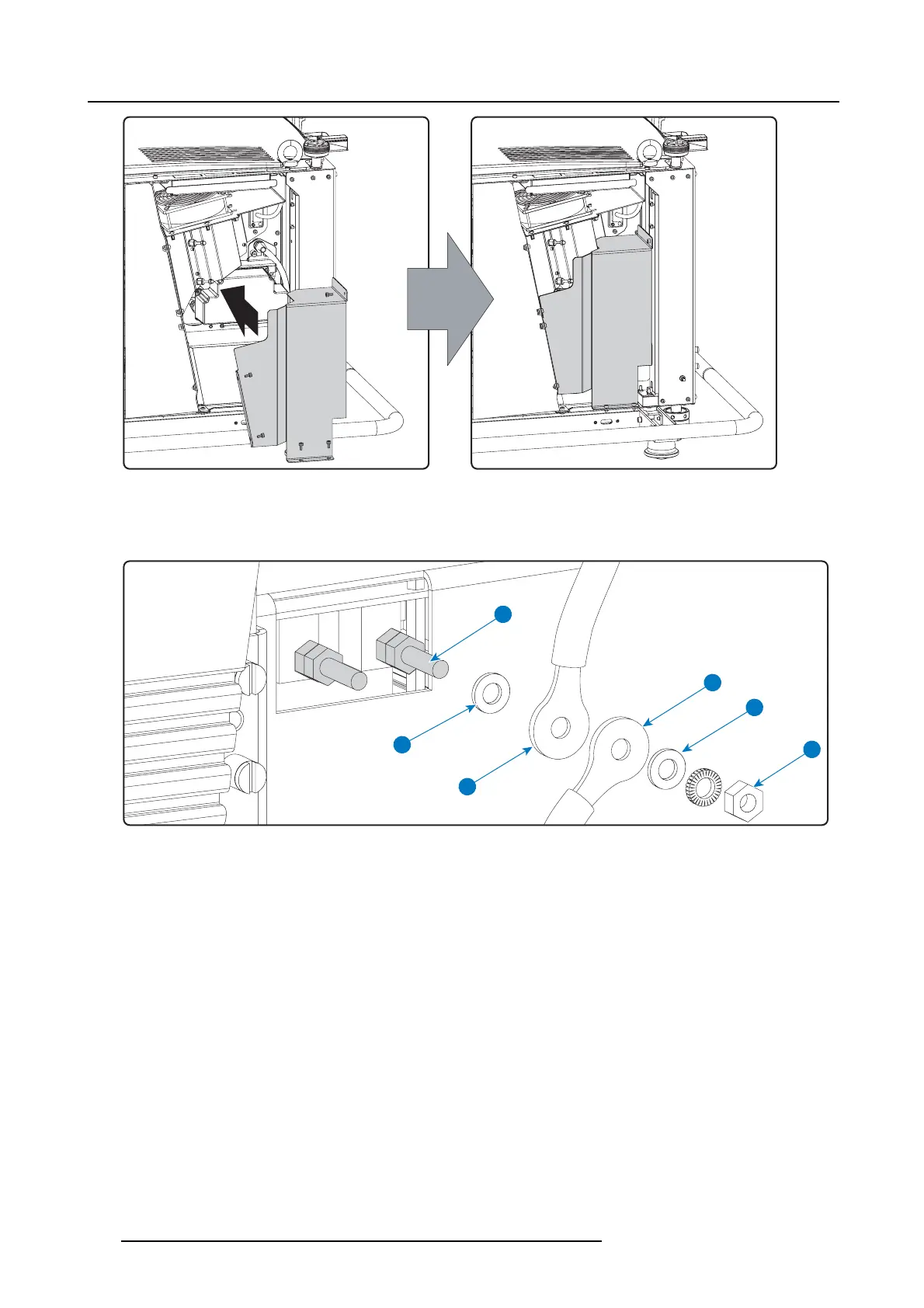
Mount SPG cover
4. C onnect the power c ables coming from the SPG module with the “LAMP OUT” sockets of the LPS m odule as illustrated.
Warning: Make sure to p lace the washers and cable eyes in correct order upon the pin as illustrated. Alwa ys use a plain
washer between the output pin and the cable eyes.
P
W
E1
E2
L
N
Image 12-9
P LPS output pin.
W Plain washer.
L Lock washer.
E1 Cable eye fr om SPG module.
E2 Cable eye from LPS unit.
NNut.
Warning: Respect the polarity of the socket and cables. Red marked c ables with the “ +” pin, black m arked cables with the “-”
pin.
186
R5905312 HDF W SERIES 24/01/2013

 Loading...


