13. HDF Light Processor
FORMATTER
RD PWR
FORMATTER
GN PWR
FORMATTER
BL PWR
SHUTTER
TEC BACK
RD
TEC BACK
GN
TEC BACK
BL
LIGHTPIPE
FRONT BLOCK
ENGINE AIR
CLO
DMD BACK RD DMD BACK GN DMD BACK BL
DMD BLOCK RD DMD BLOCK GN DMD BLOCK BL
A
E
B C D
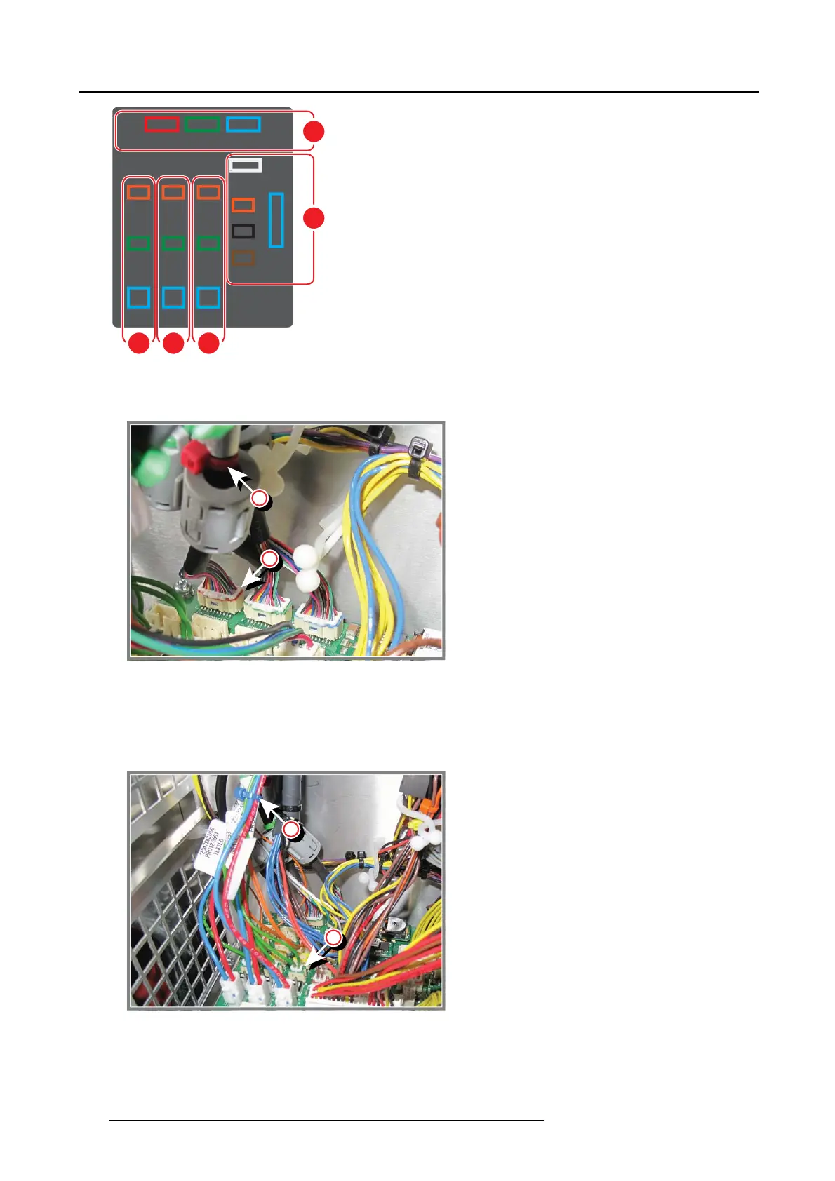
Image 13-12
Schematic overview of the electrical connectors on the Power Distribution Board
- A: A colored cable tie (1) is m ounted on the formatter cables. T his color must correspond with the color of the formatter
connector seats (2).
1
1
1
2
Image 13-13
Color coding of the formatter cab les
- B,C&D:
1) Each connector group (B , C & D) corresponds with a bunch of wires (with 3 connectors) and represents a specific color (B
= red, C = gr een & D = blue). This color must correspond with the colored cab le tie (3) mounted on each bunch of wires.
2) Couple the 3 connectors of each bunch: first the biggest connector, then the green and orange connector (according to
the color of the connector seats (4) on the board).
1
3
4
Image 13-14
Connecting the DMD cables
- E: The connector seats and wires e ach have a different color. Couple the corresponding colors.
8. P lace the light processor cover on top of the projector (1) so that the hooks (H) on both sides match with the holes (F).
Slide the cover backwards until the hooks slide under the top frame (2).
200
R5905312 HDF W SERIES 24/01/2013

 Loading...


