13. HDF Light Processor
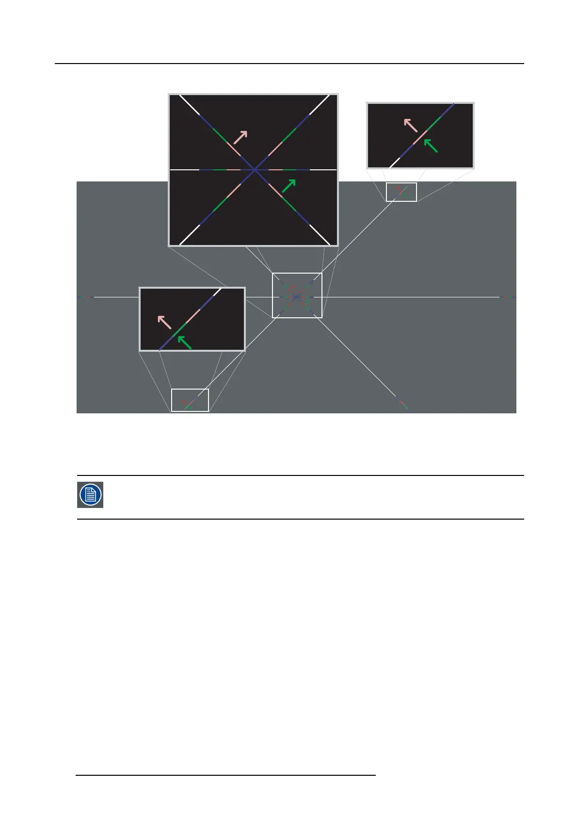
Convergence test pattern
4
1
2
5
3
6
3
6
2
5
4
1
Image 13-25
The test pattern illustrated above is sp ecially
designed for convergence purposes. T he test pattern has three red arrows numbered
from 1 to 3 and three green arrows numbered from 4 to 6. These numbers and colors correspond with the numbers and colors of
the extended control knobs. The direction of the arrow shows the mov ement of the cha nnel color (red or green) when turning the
corresponding knob in the dire ctio
n indicated by the arrow marked on the knob.
The three convergence control knobs of one channel stand in relation with each other. So, a change to one
of them will also effect the adjustment results of the two others. Therefore, all three control knobs have to
be alternately and repeatedly adjusted until the projected color is perfectly converged with the blue reference
color of the test pattern.
Adjustment range
• The adjustment range is limited to approxim ately 30 pixels in both directions.
• One turn (360°) of a control knob relates to an approximately 30 pixel displac ement on the screen.
• When changing the adjustment direction there will be some play.
210
R5905312 HDF W SERIES 24/01/2013

 Loading...


