© AGRGS 2016 | Data subject to change without notice
67385867493098462 | en, eu, V5, 07. Oct 2016, page 18
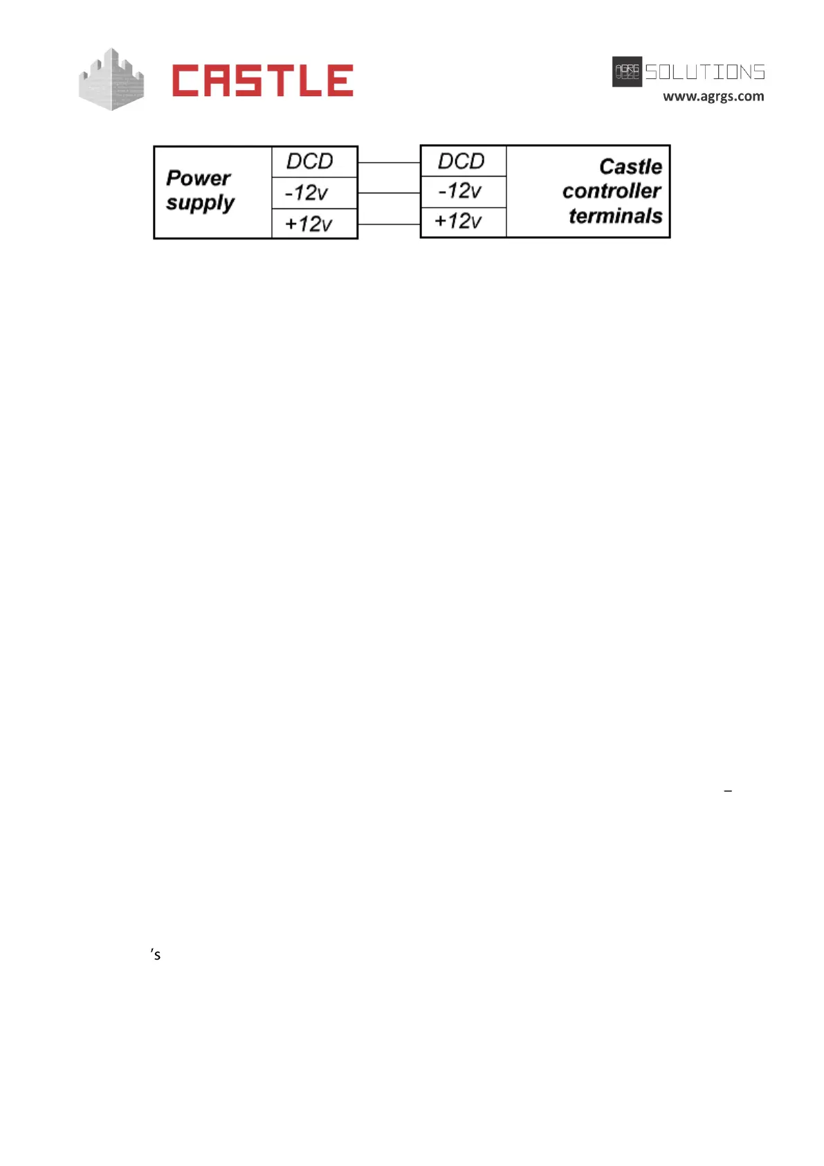
Pic 3. Connecting power supply to the controller
For connection, you can use any cable of suitable cross-section (not less than 0.75 mm²), e.g. flat
vinyl-sheath vinyl insulated cord, universal flat flexible cable, universal flat cable, vinyl-sheath
connecting wire, or flexible vinyl-sheath vinyl insulated power cable (VV-F, for external wiring).
The DCD line is an auxiliary input used by the controller to diagnose the state of the power supply
voltage. The DCD input is controlled by closing it to negative side of power supply (through OC or
"Dry contact" output) or by a low logic level voltage (0... 0.5V). When operating this input by logic
levels, the maximum voltage on it should not exceed 3.3V.
The logic zero voltage on this input corresponds to PSU functioning from the mains.
E.g., some models of "SCAT" and "RIP" UPS have output corresponding to the above indicated
requirements. If the DCD line is not used, DCD jumper must be set on the controller board (set by
default).
Note:
1. When using the BBP-20 UPS, it is recommended to install an additional battery
protection device into it (e.g. UZA-12 or BKA).
2. When using PSU in metal casing, it is necessary to connect a protective ground line to
it.
3. If actuators have floorings accumulating static electricity, it is recommended to
ground actuators themselves.
6.3 Connecting readers and contactors. Overview
The controller can be connected to up to four readers supporting a standard output interface
Wiegand-26, Wiegand-34 or Touch memory.
Definition of reader interface types is done automatically at the time of supplying a voltage to the
controller.
Each reader is connected to an identical terminal unit, which is marked on the board as PORT1,
PORT2, PORT3, and PORT4.
The purpose and the number of connected readers and contactors are described in this
document sections on specific configurations of equipment serviced by the controller.
6.3.1 General rules for connecting contactless card readers
1. Readers are located in places that are convenient for presenting access cards.
Recommended mounting height, defined ergonomically, is 1.1 to 1.4 meters from the
floor level.