© AGRGS 2016 | Data subject to change without notice
67385867493098462 | en, eu, V5, 07. Oct 2016, page 41
ON using an electric motor lock for the first door.
ON using an electric motor lock for the second door.
Table 17. Setting CONF1 toggles to work with electric motor locks
Before enabling the access point, which is servicing an electric motor lock with no built-in control
unit, you need to make its mandatory settings. To do this, run Control Program, select Doors tab,
select the desired controller from the list, click Settings, and uncheck Show only basic settings.
Then make the following settings:
● Lock control impulse length (pulse duration) set the value that provides a guaranteed
unlocking and locking of a specific instance of the lock. The time for these types of locks
may amount several seconds. E.g., you can begin with 4 seconds. If the lock unlocks or
locks not completely increase the time. If the unlocking/locking cycle should be
completed more quickly reduce the duration, leaving a small reserved time frame.
● Power on electromagnetic lock > After door is closed.
● Lock activation delay after triggering a door closing sensor (closing reed switch), the
controller starts the countdown, after which "Lock On" command will be sent. You should
set a time, which would be enough for the door to reach fully closed position after reed
switch actuation. Alternatively: you can set up a guaranteed time frame, e.g. 2 seconds.
After settings are done, press OK. All settings will be applied automatically.
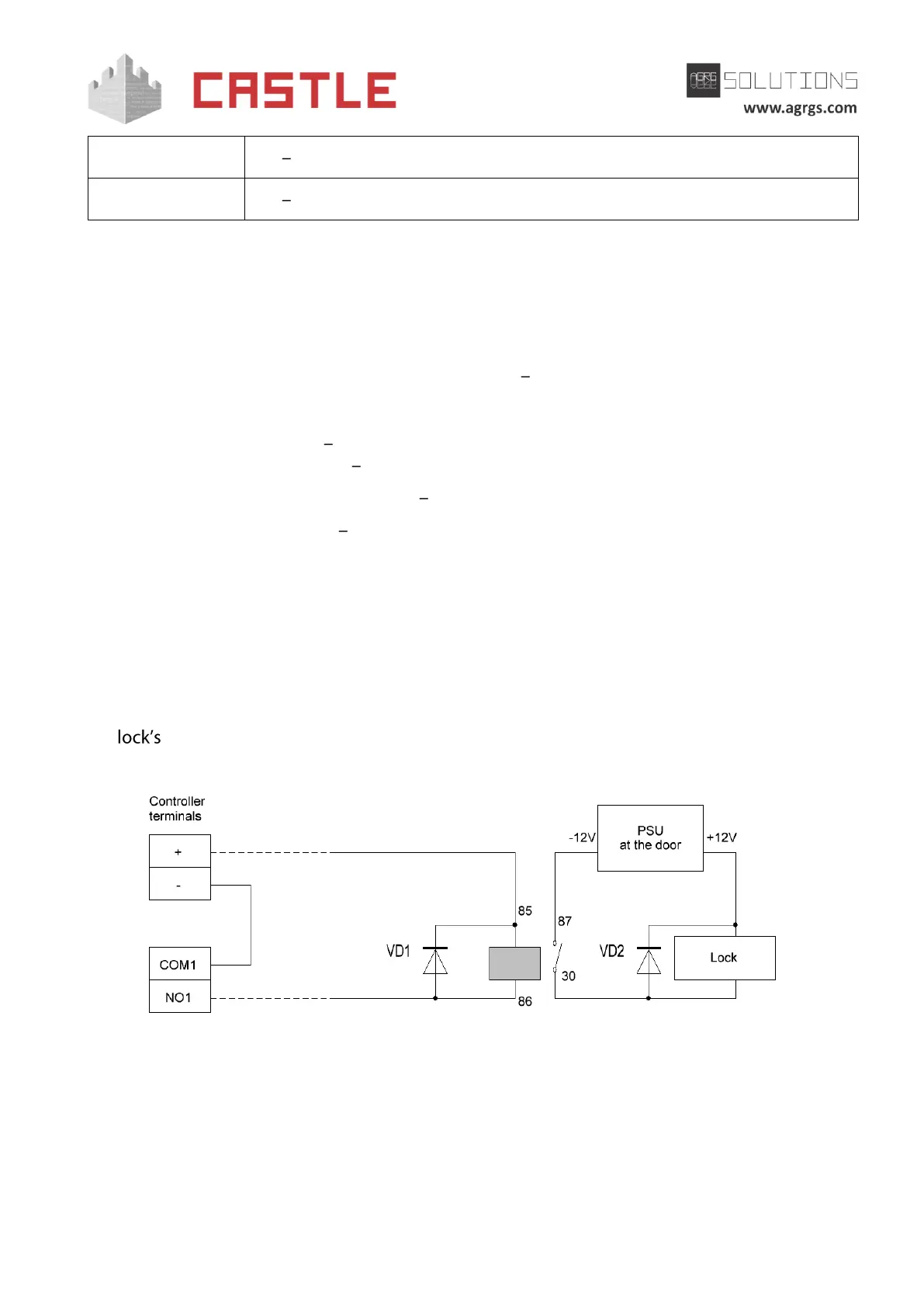
8.3.6 Example of connecting the lock that is too far from the controller
If there is a great distance from the controller to the door (70-100-150 meters), voltage drop across
the power supply wires starts to play a significant role. For the stable operation, the following
circuit can be applied:
Pic B. Example of connecting an electromagnetic lock of the first door at a great distance from the controller
An additional power supply and a relay are to be installed at the door. The controller controls the
low-current load in form of relay coil. The voltage drop across long connecting wires is minimal and
does not block actuation of the relay, whose contacts connect an additional power directly to the
lock.