© AGRGS 2016 | Data subject to change without notice
67385867493098462 | en, eu, V5, 07. Oct 2016, page 24
If firewalls are used in the IP-network for the normal controller operation, it is necessary to allow a
free exchange of UDP-datagrams between the server and the system controllers on ports 3303 and
3305.
6.4.3 Connecting RS485 communication line
The RS485 communication line is an industrial network with the bus topology, i.e. connection of all
devices integrated in this line is made in series, one after the other.
The electrical characteristics of RS485 interface allow creating communication line segments up to
1200 meters long if complied with the installation rules.
The communication line is laid with UTP Cat. 5 cable type or special cables. E.g., for internal wiring
solid or porous polyethylene insulated, shielded, PVC sheathed cable; for outdoor wiring solid or
porous polyethylene insulated, shielded, UV stabilized sheathed cable (XLPE). You can use free
communication lines laid on an object with Cat. 3 cable or higher (LAN, telephony). It is not allowed
to lay communication lines next to AC power cables and control cables of high-powered devices.
If the controller terminates a line, RT (line terminator on), PA and PB (suspender resistors on)
jumpers must be set.
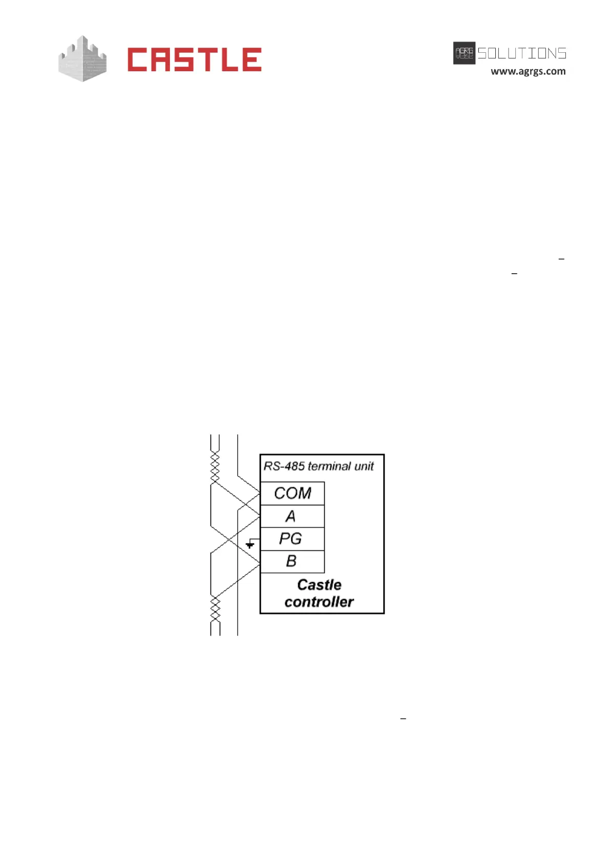
The communication line is connected to terminals A (first wire of a twisted pair), B (second wire of a
twisted pair) and COM (common), the protective grounding is connected to PG terminal. As a COM
wire, you should use any available cable wire, except for the shield.
Pic 10. Connecting the RS485 communication line to the controller, which is not terminating a line
When connecting, you should observe one correspondence of the A and B wires of communication
line on all controllers and converters connected to this line. All the A terminals should be
connected by the first wire of a twisted pair, and all the B terminals by the second wire of the
same pair.