© AGRGS 2016 | Data subject to change without notice
67385867493098462 | en, eu, V5, 07. Oct 2016, page 93
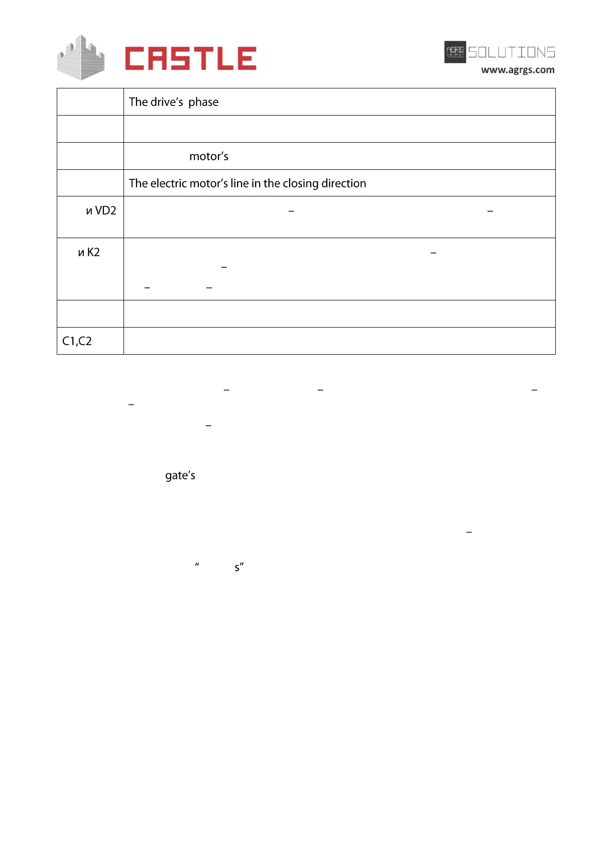
General line of the drive electric motors
The electric line in the opening direction
Protective diode (direct current at least 1A, maximum reverse voltage not less
than the relay voltage supply. E.g., 1N4007).
Power relays, coil powered by DC current, switching current not less than 10A,
switching voltage not less than ~240V.
K1 CLOSE, K2 OPEN.
47Ohm resistor, 0.5W, spark suppression circuit
0.033uF capacitor, 600V, spark suppression circuit
Before enabling the access point, you need to make its mandatory settings.
To do this, run Control Program select Doors tab select the desired controller from the list
click Settings uncheck Show only basic settings. Then make the following settings:
● Gate control mode select Straight drive direction (Direct drive control) from the drop-
down menu.
● Set Time to open/close gate sections in direct gate control mode equal to about 1.1
times of the real opening (closing) time. E.g., if the gate opens fully within 10
seconds, then the parameter value must be equal to 11 seconds.
● Set Max waiting time before autoclosing an opened gate as desired.
● Delay between sector motors activation in direct gate control mode 1 second.
● Set Gate sensor activation delay within 0.5-2.0 seconds. This parameter is used to ignore
short-term sensor release when detecting passing vehicles with a trailer or other parts
that are transparent to the sensor.
● Other parameter values are not fundamental and may be left at their default values.
After setting up, click OK. All the parameter values will be applied automatically.
10.8 Connecting FAAC drives. Overview
In this section, you can find circuit samples for connecting FAAC 596MPS, 596BPR, 610MPS, and
615BPR barriers to FAAC 540BPR and FAAC 452MPS gate drives.