© AGRGS 2016 | Data subject to change without notice
67385867493098462 | en, eu, V5, 07. Oct 2016, page 49
9. Connecting turnstiles
9.1 Connecting turnstiles. Overview
You can connect the following equipment to the controller:
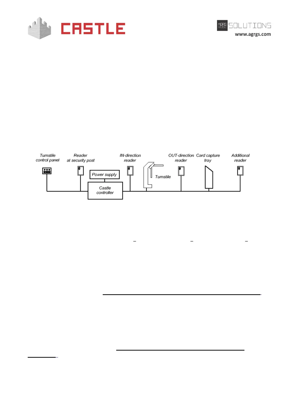
● Turnstile
● Control panel
● IN-direction reader
● OUT-direction reader
● Additional readers for capturing visitor passes or for registering passages at an
inappropriate time with the security authorization.
Pic 30. Example of connecting equipment in Turnstile configuration
The controller supports a variety of options for turnstile control and handling the passage sensor
data. The turnstile is controlled via relay contacts located on the controller board. Each relay has a
contact group working on switching (COM common contact, NC normally closed, NO normally
open).
Two options of turnstile control are supported:
1. Potential control:
When the controller grants a passage, a respective relay is activated, which is responsible for the IN
(relay 2) or OUT (relay 1). The relay switching time while waiting for passage is adjustable, it is set to
5 seconds by default (see. Sec. 15 Appendix 3. The controller numeric configuration parameters,
D0020 parameter). After the time-out or when the passage is over, the relay returns to an inactive
state locking the turnstile.
2. Pulse control:
When the controller grants a passage, a respective relay is briefly activated, which is responsible for
the IN (relay 2) or OUT (relay 1). After the time-out or when the passage is over, relay 3 triggers for a
short time, locking the turnstile. The duration of relay switching in pulse control mode is adjustable;
the default value is 200 ms (see Sec. 15 Appendix 3. The controller numeric configuration
parameters, D0024 parameter).
Three options of handling the passage sensor data are supported: