© AGRGS 2016 | Data subject to change without notice
67385867493098462 | en, eu, V5, 07. Oct 2016, page 94
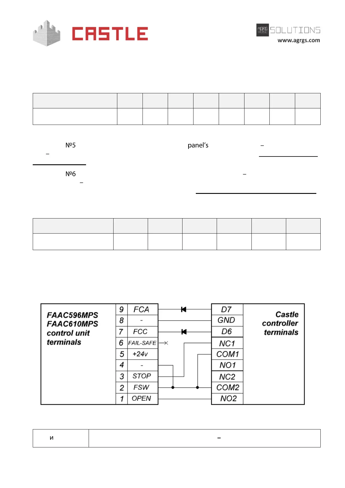
10.8.1 Connecting FAAC 596MPS and FAAC 610MPS barriers
To connect to the control panel of FAAC 596MPS and FAAC 610MPS barriers, you need to switch
the controller to the third-party gate controller handling mode according to the logic defined in
the Control Program.
Table 65. Settings of CONF1 dip-unit toggles for operating with FAAC 596MPS and FAAC 610MPS
The toggle selects the normal state of the control STOP button. ON normally closed,
OFF normally open. For the wiring diagram of the control panel, refer to Sec. 10.5 Connecting the
gate control panel.
The toggle selects the configuration of vehicle presence sensors. ON only one (the central) is
connected, OFF all three are connected (at the entrance, in the center and at the exit). For the
wiring diagram of vehicle presence sensors, refer to Sec. 10.6 Connecting vehicle presence sensors.
The programing micro toggle switches of FAAC 596MPS and FAAC 610MPS control units should be
set in the position described in the following table.
Table 66. Setting FAAC 596MPS and FAAC 610MPS programing micro toggle switch
«X» sign in the "Toggle position" means that this switch performs the function that does not affect
the ACS operation, and it must be put in the required position according to the original instructions
for FAAC 596MPS and FAAC 610MPS control units.
Pic 93. Connecting the FAAC 596MPS and FAAC 610MPS barrier control unit
Schottky diodes (minimum reverse voltage 30V, e.g., 1N5819).