© AGRGS 2016 | Data subject to change without notice
67385867493098462 | en, eu, V5, 07. Oct 2016, page 21
● LED G reader green LED, usually combined with a sound emitter, LED R reader
red LED.
● Connection of LED1 and LED2 indication lines can be omitted if the reader is
configured for internal indication control.
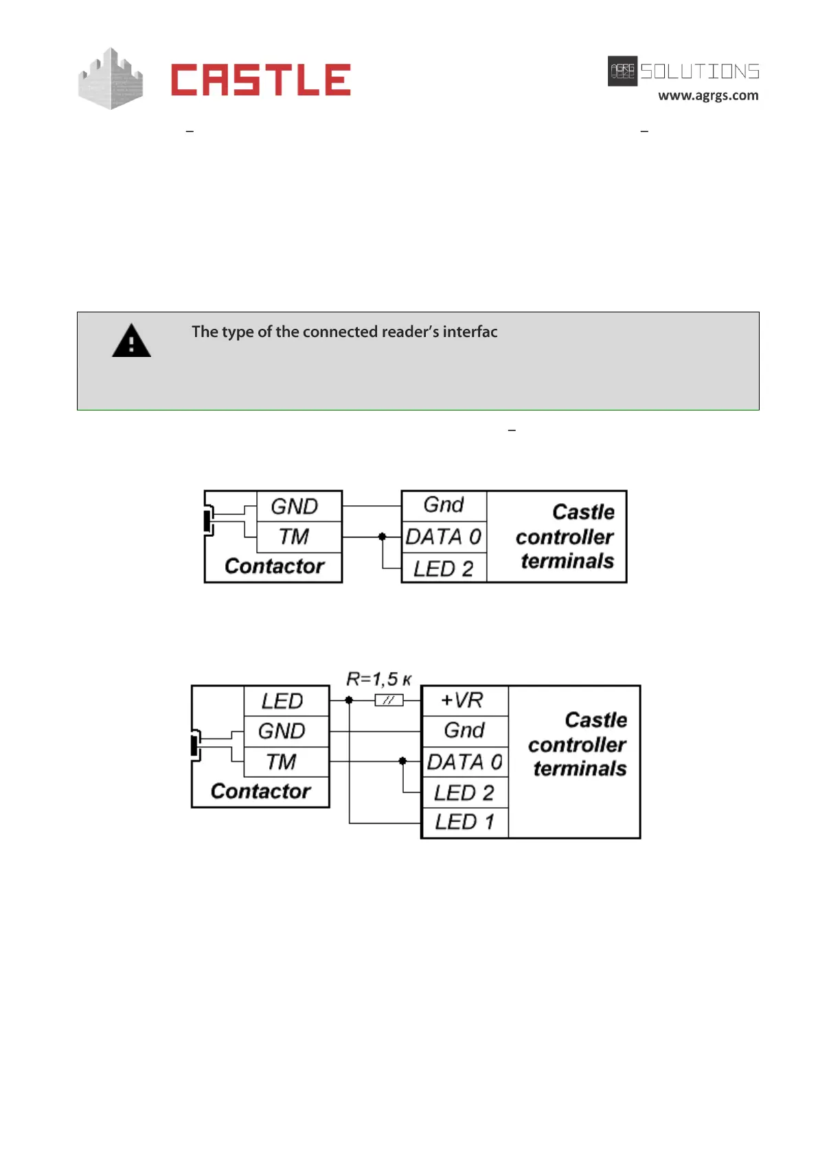
6.3.3 Connecting contactors and Touch memory readers
The electrical properties of Touch memory standard interface provide a guaranteed reader
connectivity range up to 15 m. In ideal conditions, the range up to 50 meters can be achieved.
e is determined by the controller at
the time of powering up. Therefore, the jumper between terminals DATA0 and
LED2 has to be set before powering up the controller, otherwise the Wiegand
interface type will be set and Touch memory reader will not work.
For connecting TM contactor, the following terminals are used GND, DATA0, LED2, and, if
necessary, LED1.
Pic 6. Example of connecting Touch memory contactor
Pic 7. Example of connecting Touch memory contactor with integrated LED 1