© AGRGS 2016 | Data subject to change without notice
67385867493098462 | en, eu, V5, 07. Oct 2016, page 102
● Set Gate sensor activation delay within 0.5-2.0 seconds. This parameter is used to ignore
short-term when detecting passing vehicles with a trailer or other parts
that are transparent to the sensor.
● Other parameter values are not fundamental and may be left at their default values.
● After setting up, click OK. All the parameter values will be applied automatically.
10.9 Connecting NICE barrier drives. Overview
In this section, you can find circuit samples for connecting WIL4, WIL6, SIGNO, and X-Bar barriers.
10.9.1 Connecting NICE WIL4 and WIL6 barriers
To connect to WIL4 or WIL6 barrier, equipped with the built-in WA20 control unit, you need to
switch the controller to the drive direct control mode.
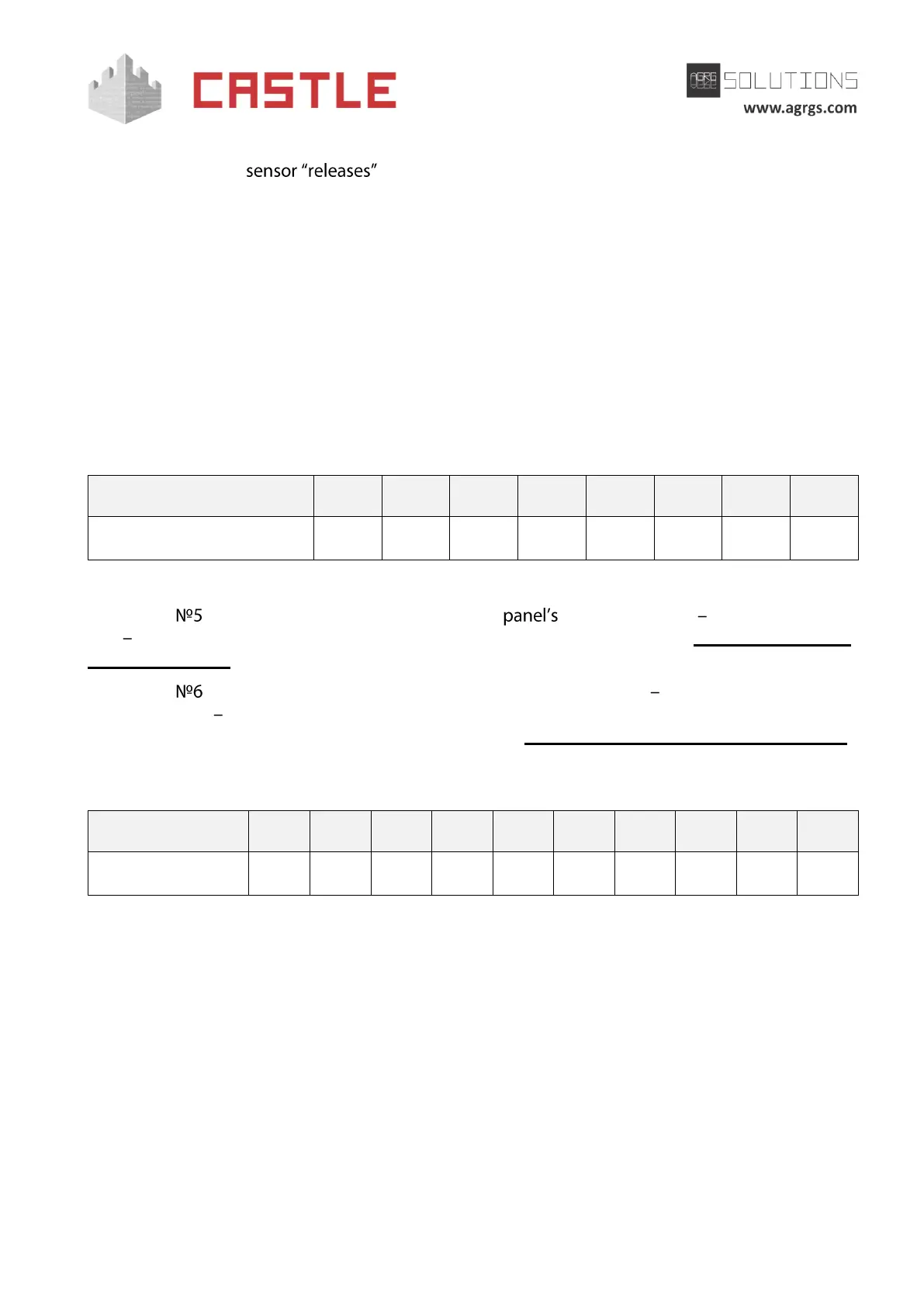
Table 73. Settings of CONF1 dip-unit toggles for operating with WA20 control unit
The toggle selects the normal state of the control STOP button. ON normally closed,
OFF normally open. For the wiring diagram of the control panel, refer to Sec. 10.5 Connecting the
gate control panel.
The toggle selects the configuration of vehicle presence sensors. ON only one (the central) is
connected, OFF all three are connected (at the entrance, in the center and at the exit). For the
wiring diagram of vehicle presence sensors, refer to Sec. 10.6 Connecting vehicle presence sensors.
To select a function, the programing micro toggle switch of WA20 control unit should be set in the
position described in the following table.
Table 74. Setting FUNCTIONS micro toggle switch on the WA20 control unit board
«X» sign in the "Toggle position" means that this switch performs the function that does not affect
the ACS operation, and it must be put in the required position according to the original instruction
for WA20 control unit.