© AGRGS 2016 | Data subject to change without notice
67385867493098462 | en, eu, V5, 07. Oct 2016, page 107
● Other parameter values are not fundamental and may be left at their default values.
● After setting up, click OK. All the parameter values will be applied automatically.
10.9.4 Connecting drives with A924 control unit
To connect to a gate drive with A924 control unit, you need to switch the controller to the third-
party gate controller handling mode according to the logic defined in the Control Program.
Table 78. Settings of CONF1 dip-unit toggles for operating with A924
The toggle selects the normal state of the control STOP button. ON normally closed,
OFF normally open. For the wiring diagram of the control panel, refer to Sec. 10.5 Connecting the
gate control panel.
The toggle selects the configuration of vehicle presence sensors. ON only one (the central) is
connected, OFF all three are connected (at the entrance, in the center and at the exit). For the
wiring diagram of vehicle presence sensors, refer to Sec. 10.6 Connecting vehicle presence sensors.
To select a function, the programing micro toggle switch on the A924 control unit board should be
set in the position described in the following table.
Table 79. Setting the micro toggle switch for selecting functions on the A924 control unit board
«X» sign in the "Toggle position" means that this switch performs the function that does not affect
the ACS operation, and it must be put in the required position according to the original instruction
for A924 control unit.
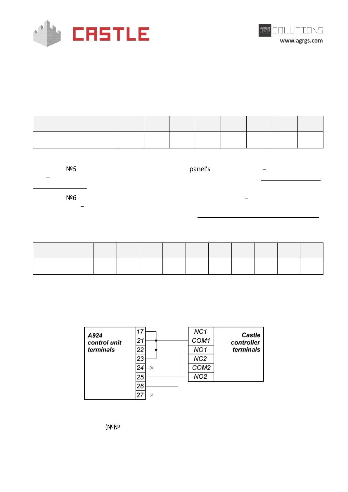
Pic 101. Connecting A924 control unit
The rest of the terminals 1-16, 18-20) are connected according to the original instruction for
A924 control unit.