© AGRGS 2016 | Data subject to change without notice
67385867493098462 | en, eu, V5, 07. Oct 2016, page 51
The controller can handle commands from three normally open buttons of the control panel. Panel
indication servicing is performed by turnstile control units.
9.3 Connecting turnstile control lines
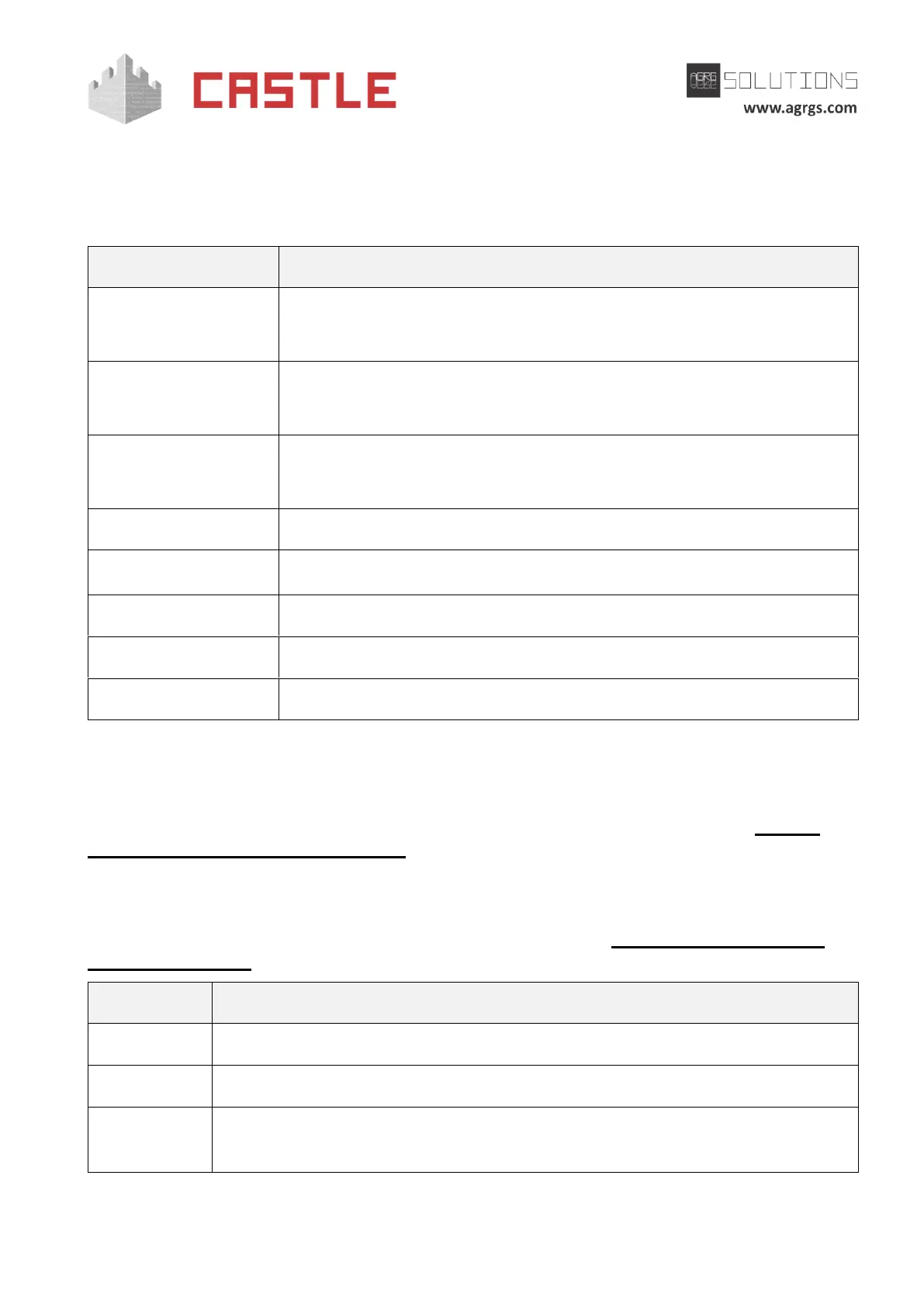
Release line in OUT direction (potential or pulse).
Release line in IN direction (potential or pulse).
Blocking line
(used only at pulse control).
OUT-passage sensor line or, in Single-wire interface, a single sensor line.
IN-passage sensor line. N/A in a Single-wire interface.
Exit button of the turnstile manual control panel.
Entry button of the turnstile manual control panel.
STOP button of the turnstile manual control panel.
Table 24. Using controller terminals for connecting turnstile control lines
You should connect control lines and passage sensor lines depending on how the turnstile is mounted,
i.e. which direction of the passage should be considered as IN and which one as OUT.
The operating logic of the controller while controlling the turnstile is described in Sec. 11.8 The
operating logic in Turnstile configuration.
9.4 Connecting readers for the turnstile
Readers are connected to the controller terminals according to Sec. 6.3 Connecting readers and
contactors. Overview.
Additional OUT direction reader. For capturing visitor passes or registering
passages at inappropriate time. It can also operate identically to the main one.