© AGRGS 2016 | Data subject to change without notice
67385867493098462 | en, eu, V5, 07. Oct 2016, page 89
10.2 Direct control of gate drives
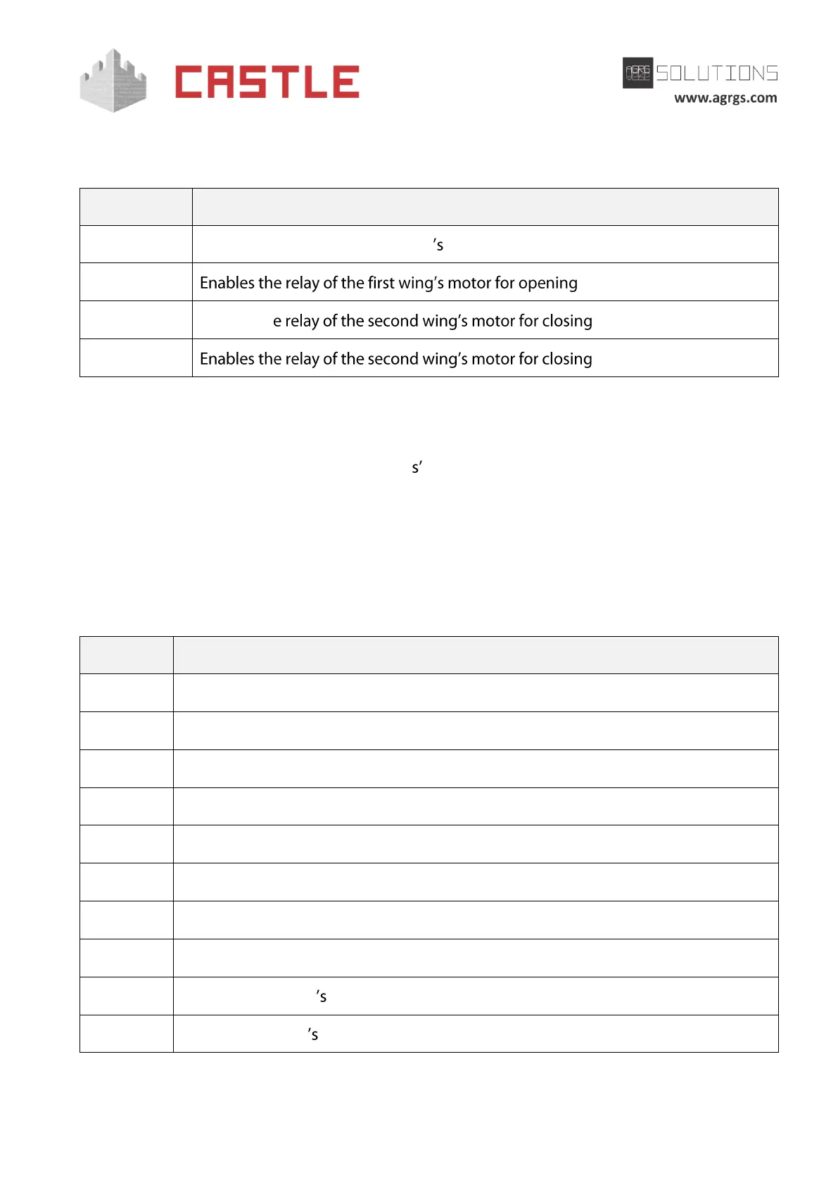
In this configuration, K1-K4 relays are used for controlling motors.
Enables the relay of the first wing motor for closing
Table 60. Using controller terminals for connecting motors
The direct connection of the gate drive to K1-K4 relay contacts is not allowed. It is necessary to use
intermediate relays designed for a switching voltage of at least ~240V and for a current of not less
than the doubled current consumption of drive motors.
10.3 Controlling a third-party gate controller (control unit)
The controller allows you to control virtually any gate drive equipped with its own control unit.
Below are specific examples and the general approach of the connection.
To manage a third-party controller, relays K1, K2, K3 and inputs D1- D7 are used. Relays, buttons
and sensors are connected according to the following table.
STOP command to a third-party controller.
OPEN or START command to a third-party controller.
CLOSE command to a third-party controller.
The sensor for detecting the vehicle presence in front of the gate when leaving.
The sensor for detecting the vehicle presence in between the gate posts.
The sensor for detecting the vehicle presence in front of the gate at the entrance.
START/ALLOW PASSAGE button on the control panel.
STOP/DENY PASSAGE button on the control panel.
Closed state sensor input.
Table 61. Using the controller terminals when controlling a third-party gate drive