© AGRGS 2016 | Data subject to change without notice
67385867493098462 | en, eu, V5, 07. Oct 2016, page 92
Output contacts of several sensors can be joined in series in order to connect them to a single
controller input. E.g., by this way, you can increase the system safety putting not one but several
photocell sensors in the operating area of the gate wings at different heights and distances from
the gate.
10.7 Connecting FAST, KRONO, ATI, and FERNI drives
To connect FAST, KRONO, ATI, and FERNI drives, you need to switch the controller to the third-party
gate controller handling mode according to the logic defined in the Control Program.
Table 64. Settings of CONF1 dip-unit toggles for operating with FAST, KRONO, ATI, and FERNI
The toggle selects the normal state of the control STOP button. ON normally closed,
OFF normally open. For the wiring diagram of the control panel, refer to Sec. 10.5 Connecting the
gate control panel.
The toggle selects the configuration of vehicle presence sensors. ON only one (the central) is
connected, OFF all three are connected (at the entrance, in the center and at the exit). For the
wiring diagram of vehicle presence sensors, refer to Sec. 10.6 Connecting vehicle presence sensors.
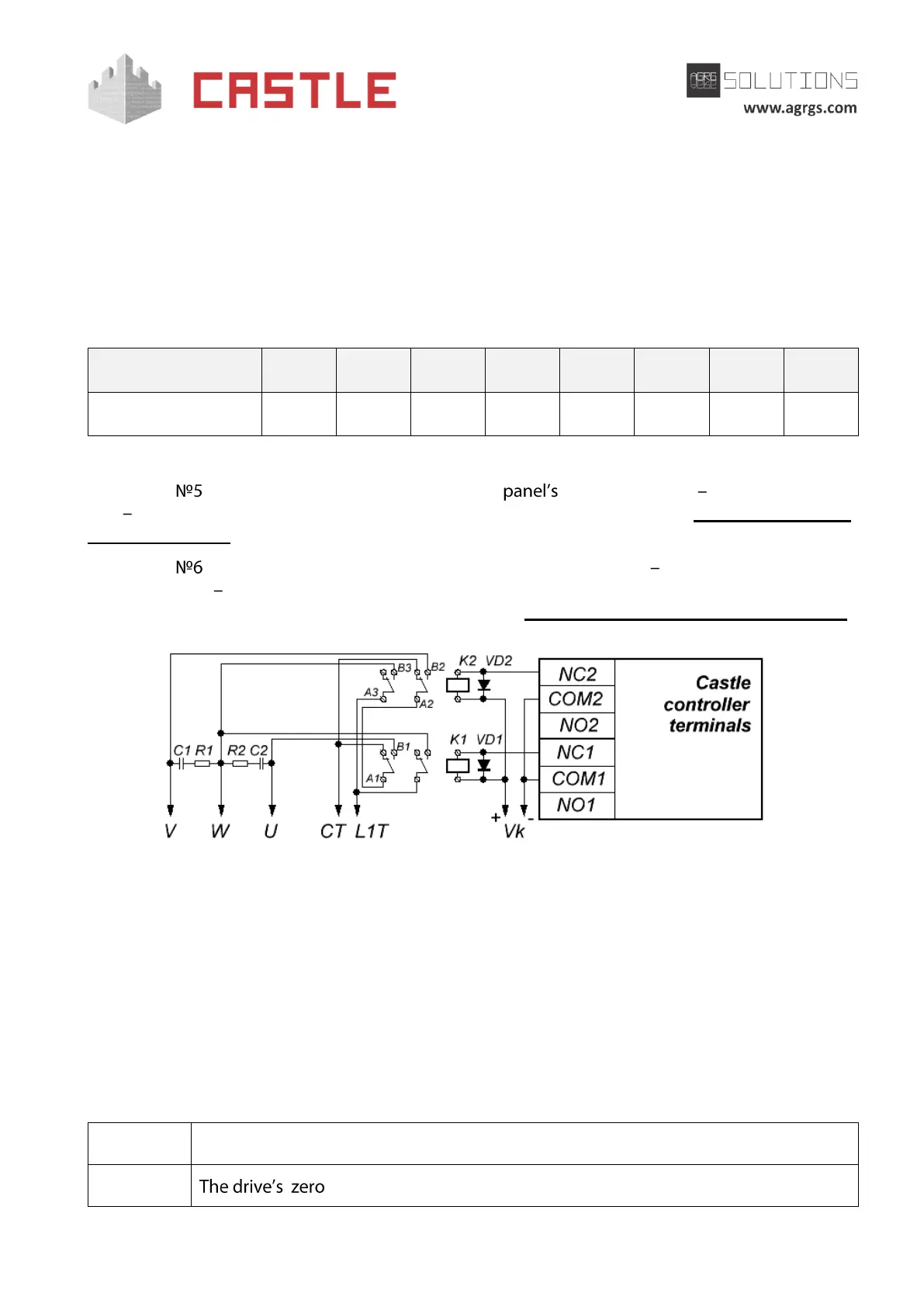
Pic 92. Example of connection to FAST, KRONO, ATI, and FERNI gate drives for direct motor control
The wiring diagram is applicable to FAST, KRONO, ATI, and FERNI drives and to any other having a
three-wire wing drive interface, consisting of a common line and two lines corresponding to the
opening and closing directions. The motion takes place when a ~220V voltage is supplied between
the general line and the relevant direction line.
The connection of one (the first) gate wing controlled by the drive (rated for 220V) is shown above.
The second wing is connected in the same manner, except for using relays 3 and 4 instead of relays
1 and 2.
Legend:
Voltage supply of K1 and L1T power relays