© AGRGS 2016 | Data subject to change without notice
67385867493098462 | en, eu, V5, 07. Oct 2016, page 124
10.11 Connecting BFT drives. Overview
In this section, you can find circuit samples for connecting drives with ELMEC1 and ELMEC2 control
units.
10.11.1 Connecting drives with ELMEC1 control unit
To connect to ELMEC1 control unit, you need to switch the controller to the third-party gate
controller handling mode according to the logic defined in the Control Program.
Table 100. Settings of CONF1 dip-unit toggles for operating with ELMEC1 control unit
The toggle selects the normal state of the control STOP button. ON normally closed,
OFF normally open. For the wiring diagram of the control panel, refer to Sec. 10.5 Connecting the
gate control panel.
The toggle selects the configuration of vehicle presence sensors. ON only one (the central) is
connected, OFF all three are connected (at the entrance, in the center and at the exit). For the
wiring diagram of vehicle presence sensors, refer to Sec. 10.6 Connecting vehicle presence sensors.
The function selection micro toggle switches on the ELMEC1 control unit board should be set in the
position described in the following table.
Table 101. Setting the micro toggle switches on the ELMEC1 control unit board
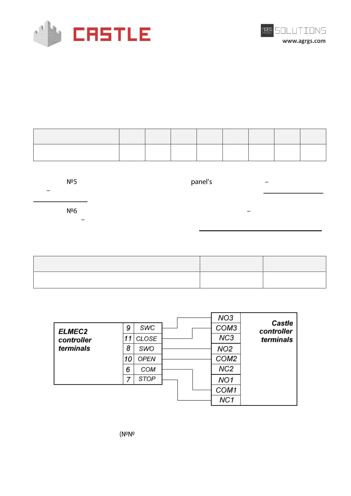
Pic 111. Connecting ELMEC1 control unit
The rest of the unit terminals 1-5, 12-15) are connected according to the original instruction
for ELMEC1 control unit.