Parameter
structure
Keypad and
display
Parameter
x.00
Parameter
description format
Advanced parameter
descriptions
Macros
Serial comms
protocol
Electronic
nameplate
Performance
Feature look-
up table
Menus 15 to 17
Fieldbus
Unidrive SP Advanced User Guide 281
Issue Number: 7 www.controltechniques.com
Effects of non-cyclic data modes on mapping parameters
If Pr x.05 has been set to enable a non-cyclic data type then during the module's initialisation the first 'I' and 'O' parameters will be checked. If either
of these parameters is already mapped to non-cyclic virtual parameter then it will be over written to make sure that it is of the correct format (1 word
CTNC or 4 word PPONC). If either of the parameters are found not to be non-cyclic virtual parameters then the first 9 parameters in the relevant
group will be shuffled up a place and the first parameter will be set for the non-cyclic channel. This means that if Pr x.19 or Pr x.29 has been set and
a non-cyclic data type has been selected this mapping could be lost.
If Pr x.05 has been set to not enable any form of non-cyclic data the first 'I' and 'O' parameters are checked. If either is set to a non-cyclic virtual
parameter then the last 9 parameters in the relevant group will be shuffled down to remove the non-cyclic channel and the last mapping parameter will
be set to 0. Non-cyclic virtual parameters placed anywhere else in the mappings won't be removed.
If Pr x.05 = 0 and Pr x.09 = 0 any non-cyclic virtual parameters in the first 'I' or 'O' parameter will be left.
A maximum of 1 non-cyclic channel can be placed in both the ‘I’ and ‘O’ parameters for each non-cyclic type. If multiple non-cyclic channels of the
same type are defined then a mapping error will be produced.
Fieldbus setup menu access
Setting an ‘I’ or ‘O’ parameter to a UT7x fieldbus setup menu must specify the slot in which the fieldbus Solutions Module is placed by using menus
15 -> 17 for slots 1 -> 3 respectively. Mapping into another fieldbus modules setup menu parameters Pr x.10 to Pr x.29 will only be allowed if that
module is in register control (Pr x.09 = 1) to prevent corruption of mapping configurations. Mapping into a Solutions Modules own setup menu by
either direct mapping or by use of the virtual fieldbus setup menu (menu 60) is not allowed. Any invalid mapping into a fieldbus setup menu will show
as a read-write mismatch error.
SM-Applications parameter access
Setting an 'I' or 'O' parameter to a SM-Applications database parameter without a slot specified will cause the fieldbus module to select the SM-
Applications fitted in the lowest numbered slot. If access to two SM-Applications is required, then the slots must be addressed specifically by using
menus 100 -> 181 (See Table 5-10). These values have been chosen to allow complete access to the SM-Applications menus and yet still keep an 8
bit menu identifier, which is needed for CT non-cyclic compatibility.
Table 5-10 Solutions Module slot equivalent menus
Advanced SM-Applications parameter mapping
Should adjacent parameters within Pr x.10 to Pr x.19 and/or Pr x.20 to Pr x.29 represent mappings to different parameters within the same SM-
Applications PLC menu (70 -> 75), or the drives application menus (18 -> 20), then the mappings will be interpreted to indicate a range.
Ranges will only be generated if the first parameter value of the adjacent pair is lower than the second parameter value.
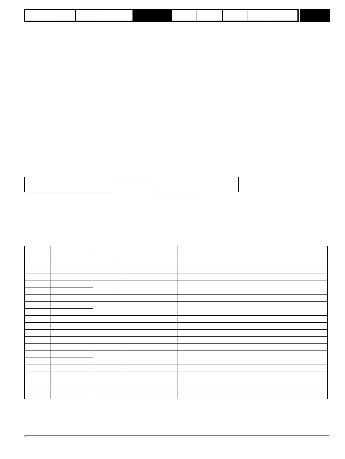
Table 5-11 illustrates a possible (although not expected) mapping configuration for a drive with a SM-PROFIBUS-DP in slot 1 and SM-Applications in
slots 2 and 3 respectively.
Table 5-11 Example 'I' and 'O' Mappings
Table 5-12 illustrates what the resulting message would look like.
Menu Slot 1 Slot 2 Slot 3
70 -> 91 – SM-Applications PLC Menus 100 -> 127 130 -> 157 160 -> 187
Mapping
parameter
Mapping
parameter setting
Data Width
Total Data Width
(Running Total in Bytes)
Comment
Pr 15.10 Pr 10.40 1*16 bit 2 Default - Status (not fixed)
Pr 15.11 Pr 2.01 1*32 bit 6 Default - Post ramp speed reference (not fixed)
Pr 15.12 Pr 4.20 1*16 bit 8 Default - % of rated load (not fixed)
Pr 15.13 Pr 130.11
5*32 bit 28
A range of 5, slot 2, SM-Applications PLC registers will be the source of
cyclic data
Pr 15.14 Pr 130.15
Pr 15.15 Pr 71.03 1*32 bit 32 A slot 2 SM-Applications parameter will source cyclic data
Pr 15.16 Pr 160.11
5*32 bit 52
A range of 5, slot 3, SM-Applications PLC registers will be the source of
cyclic data
Pr 15.17 Pr 160.15
Pr 15.18 0 0 52 Channel disabled
Pr 15.19 0 0 52 Channel disabled
Pr 15.20 Pr 6.42 1*16 bit 2 Default – Control word (not fixed)
Pr 15.21 Pr 1.21 1*32 bit 6 Default – Pre-set speed reference (not fixed)
Pr 15.22 Pr 4.08 1*32 bit 10 Default – Torque reference (not fixed)
Pr 15.23 Pr 130.01
5*32 bit 30
A range of 5, slot 2, SM-Applications PLC registers will receive cyclic
data
Pr 15.24 Pr 130.05
Pr 15.25 Pr 131.03 1*32 bit 34 A slot 2 SM-Applications parameter will receive cyclic data
Pr 15.26 Pr 160.01
5*32 bit 54
A range of 5, slot 3, SM-Applications PLC registers will receive cyclic
data
Pr 15.27 Pr 160.05
Pr 15.28 0 0 54 Channel disabled
Pr 15.29 0 0 54 Channel disabled
http://nicontrols.com