Parameter
structure
Keypad and
display
Parameter
x.00
Parameter
description format
Advanced parameter
descriptions
Macros
Serial comms
protocol
Electronic
nameplate
Performance
Feature look-
up table
Menus 15 to 17
Fieldbus
Unidrive SP Advanced User Guide 283
Issue Number: 7 www.controltechniques.com
The value set in Pr x.30 will affect the drive 'parameter default' sequence and will be cleared once defaults are loaded.
If Pr x.30 = 0 and a Unidrive SP default is requested then step 4 will be bypassed.
If Pr x.30 = 1 and a Unidrive SP default is requested then step 4 will be included.
1. Fieldbus communication will be stopped.
2. The drive will load its default parameter values and automatically save them to its EEPROM.
3. Solutions Module will over-write any general drive default values with fieldbus specific ones. e.g. if a SM-DeviceNet is fitted and it sees that 65535
(general drive default) is present in the node address parameter the module will over-write this with 63.
The module also monitors for "general drive default" values in the background task and over-writes as necessary.
4. Default Solutions Module parameter settings will be saved within the Solutions Modules Flash memory.
5. The module will reset itself.
6. The Solutions Module will perform its standard start-up procedure using the default values.
The value set in Pr x.31 will affect the drive 'parameter save' sequence and will be cleared once parameters are saved as follows:
If Pr x.31 = 0 and a Unidrive SP save is requested:
1. The Unidrive SP will save its parameters.
If Pr x.31 = 1 and a Unidrive SP save is requested:
1. The Unidrive SP will save its parameters.
2. Fieldbus communication will be halted immediately.
3. Fieldbus menu parameters will be saved within the Solutions Module Flash.
4. The module will reset itself.
5. The Solutions Module will perform its standard start-up procedure using the saved values.
The ability to save the Fieldbus specific parameters within the Solutions Module enables the user to place a pre-programmed module into a
replacement drive and retain its settings, see Pr x.33.
In most cases the user can simply perform a Unidrive SP parameter save - this is enough to ensure that the system will recover from a power supply
cycle and does not result in an interruption to Fieldbus communication.
The parameter will be continuously polled and cleared once 'Request to reinitialise' is performed. When set, the following will occur:
1. Fieldbus communication will be stopped.
2. Pr x.32 will be cleared.
3. Standard start-up procedure will be performed using current fieldbus configuration values
Setting the value 1,070 in any parameter 0 and pressing the drive reset button will cause any modules fitted in the drive to be reset.
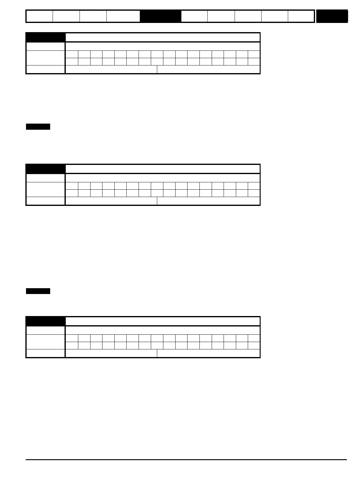
x.30 Load option defaults
Drive types Open-loop, Closed-loop vector, Servo, Regen
Coding
Bit SP FI DE Txt VM DP ND RA NC NV PT US RW BU PS
1111
Default All drive types 0
x.31 Save option parameters
Drive types Open-loop, Closed-loop vector, Servo, Regen
Coding
Bit SP FI DE Txt VM DP ND RA NC NV PT US RW BU PS
111
Default All drive types 0
x.32 Request to reinitialise
Drive types Open-loop, Closed-loop vector, Servo, Regen
Coding
Bit SP FI DE Txt VM DP ND RA NC NV PT US RW BU PS
11
Default All drive types 0
NOTE
NOTE
http://nicontrols.com