Menus 15 to 17
SM-SLM
Parameter
structure
Keypad and
display
Parameter
x.00
Parameter
description format
Advanced parameter
descriptions
Macros
Serial comms
protocol
Electronic
nameplate
Performance
Feature look-
up table
306 Unidrive SP Advanced User Guide
www.controltechniques.com Issue Number: 7
The encoder has a marker channel and this is used to correct the absolute position within a revolution after power-up. After passing through the
marker this bit is set and the zero offset parameter is updated with the difference between zero of the encoder position and the marker. This error is
due to the initial angle calculation using the single cycle SinCos. The power-up single cycle SinCos method has a maximum error of ±3°.
This parameter converts the drive phase angle (Pr 3.25) into an SLM EEPROM (CT Coder) nameplate flux offset value. The drive is the electrical
angle offset in degrees. The SLM flux offset is the mechanical offset in 65,535 places per revolution offset by 120°.
This parameter is used to set the mask used on the fine position sent from the SLM module to the Solutions Module. 1024 lines results in 6 extra bits
of fine position information being used. This takes the full position resolution to 22 bits. A 2046 line encoder uses 7 extra bits of fine position etc.
Indicates the software version of the SLM module fitted to the motor. This is SLM Pr 100 which needs to have been transferred if in HOST mode. The
format is p.vvv where p is the page and vvv is the software version of the page.
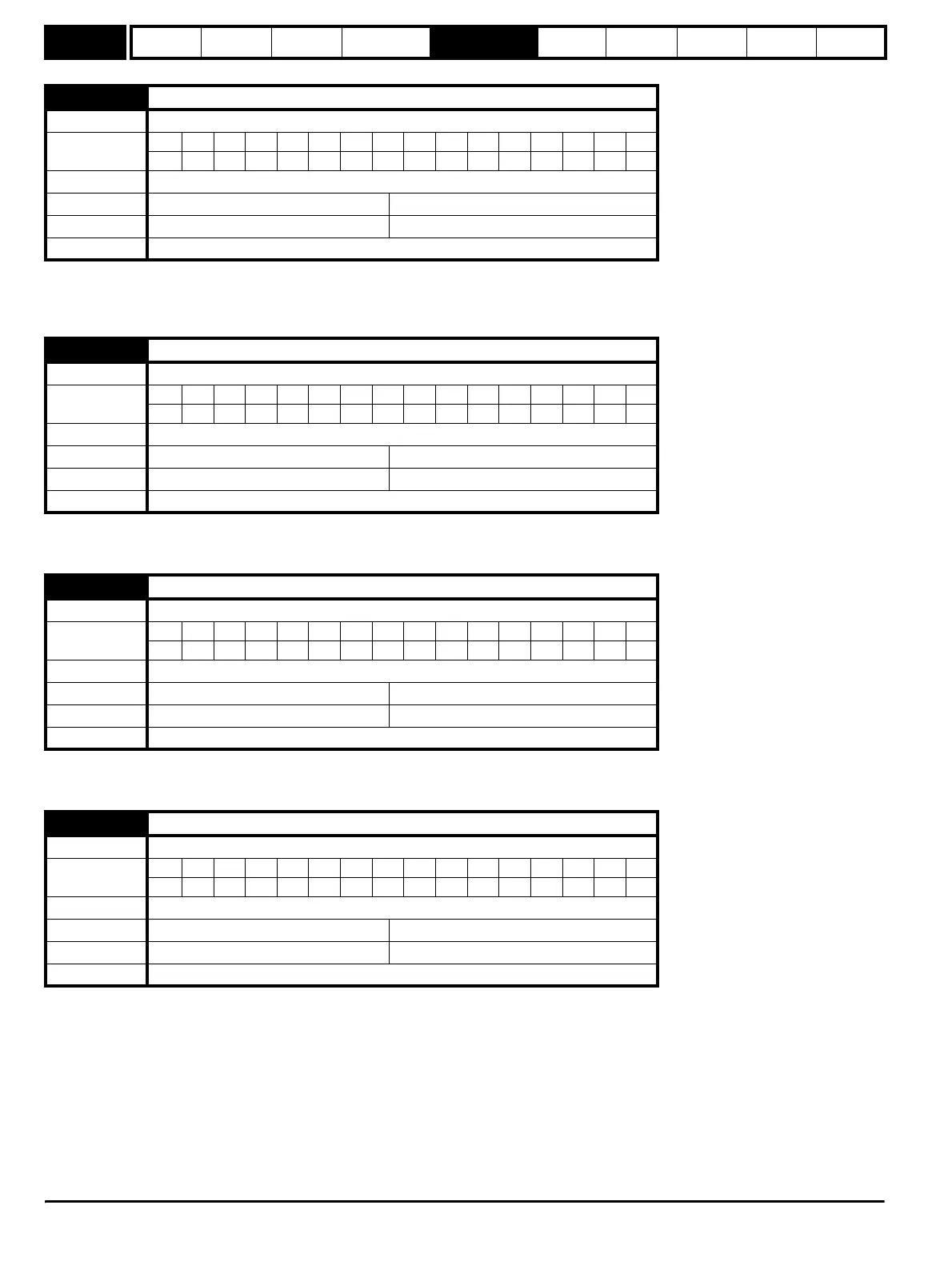
x.08 Marker pulse received indicator
Drive modes Open-loop, Closed-loop vector, Servo, Regen
Coding
Bit SP FI DE Txt VM DP ND RA NC NV PT US RW BU PS
11
Operating mode
Host, Encoder only
Range Open-loop, Closed-loop, Servo, Regen OFF (0) or On (1)
Default Open-loop, Closed-loop, Servo, Regen OFF (0)
Update rate Backgroud
x.09 SLM converted flux offset
Drive modes Open-loop, Closed-loop vector, Servo, Regen
Coding
Bit SP FI DE Txt VM DP ND RA NC NV PT US RW BU PS
1
Operating mode
Host, Encoder only
Range Open-loop, Closed-loop, Servo, Regen 0 to 65,535
Default Open-loop, Closed-loop, Servo, Regen 0
Update rate Backgroud
x.10 Encoder lines per revolution
Drive modes Open-loop, Closed-loop vector, Servo, Regen
Coding
Bit SP FI DE Txt VM DP ND RA NC NV PT US RW BU PS
111
Operating mode
Host, Encoder only
Range Open-loop, Closed-loop, Servo, Regen 0 to 50,000
Default Open-loop, Closed-loop, Servo, Regen 1024
Update rate Backgroud
x.11 SLM software version
Drive modes Open-loop, Closed-loop vector, Servo, Regen
Coding
Bit SP FI DE Txt VM DP ND RA NC NV PT US RW BU PS
31
Operating mode
Host, Encoder only
Range Open-loop, Closed-loop, Servo, Regen 0.000 to 9.999
Default Open-loop, Closed-loop, Servo, Regen 0.000
Update rate Backgroud
http://nicontrols.com