S0602170K
Page 80
Axle (ZF AP 420R)
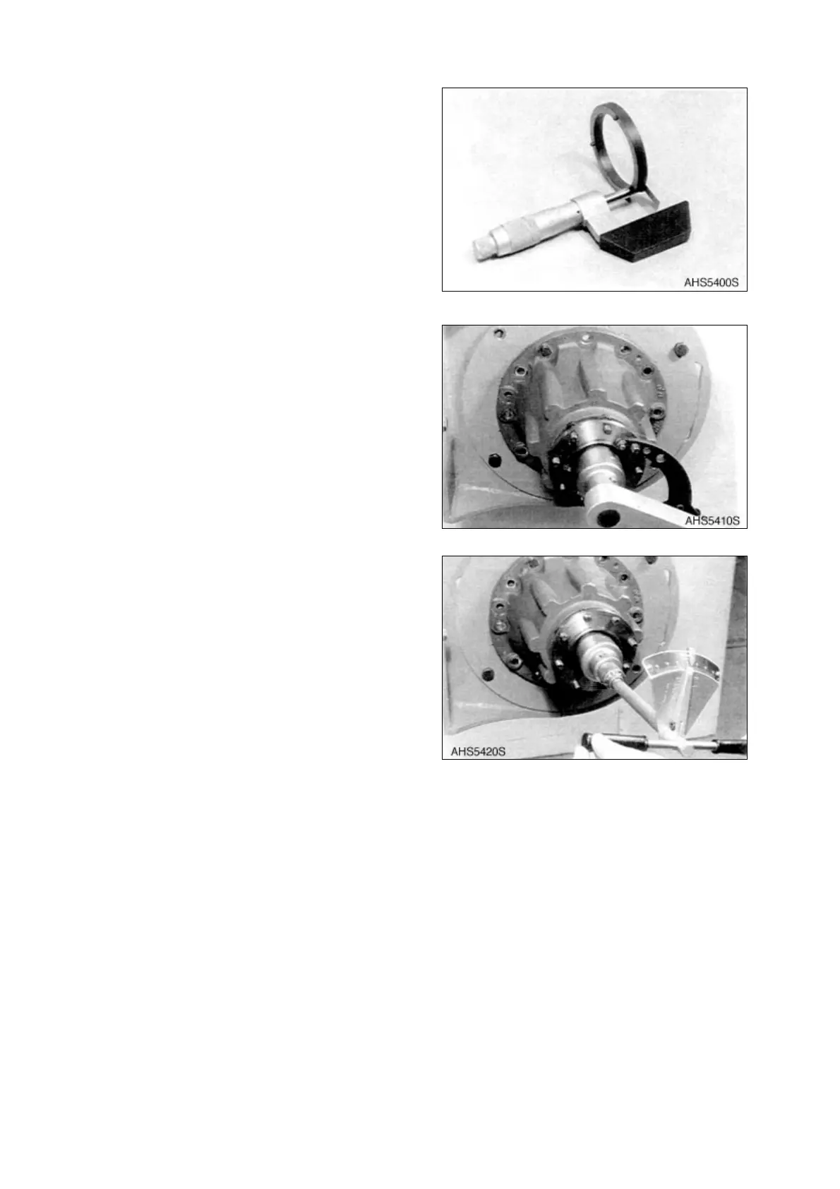
7. Take off measuring ring and determine
dimension "X" see Figure 161.
• Dimension "X" e.g. s = 8.55 mm
(0.3366 in).
NOTE:
Dimension "X" corresponds to
the thickness of the spacer to
be installed.
NOTE:
Lay spacer (e.g. s = 8.55 mm
(0.3366 in)) instead of the
measuring ring over the drive
pinion end. Install drive pinion
again.
8. Replace drive flange, install washer and
tighten slotted nut
NOTE:
Torque limit:
RK 1,100 Nm (810 ft lb)
LK 1,200 Nm (885 ft lb)
CK 700 Nm (515 ft lb)
NOTE:
When tightening, mate several
full revolutions of the drive
pinion in both directions.
9. Check rolling resistance
NOTE:
If the required rolling resistance
is not obtained correct again
with one corresponding spacer.
Figure 165
Figure 166
Figure 167