S0708470K
Page 12
Steering and Brake Pump (Denison T67DB Series)
NOTE:
4535V models are slightly different from the models shown in Figure 7. Screws (4) are
longer and fasten cover (5), inlet housing (19), and body (38) together. Screws (18) are
omitted.
BASIC PUMP DISASSEMBLY
1. Thoroughly clean pump exterior.
2. Use a prick punch and mark position of cover (37) and body (1) with respect to inlet housing (22) for
correct reassembly.
3. Support the pump on blocks or clamp body (1) in a vise. Remove four cover screws (38) and lift cover
(37) off pump.
NOTE:
If a vise is used, use protective jaws to avoid damage to body and its machine surfaces.
4. Remove U-ring (36), O-ring (35), seal ring (34), and O-ring (33) from cartridge kit (39) and discard.
5. Pull and/or pry out center cartridge kit (39) from inlet housing (22).
6. Remove four screws (23) from inlet housing (22), then left off housing.
7. Pull shaft end cartridge kit (40) from body (1).
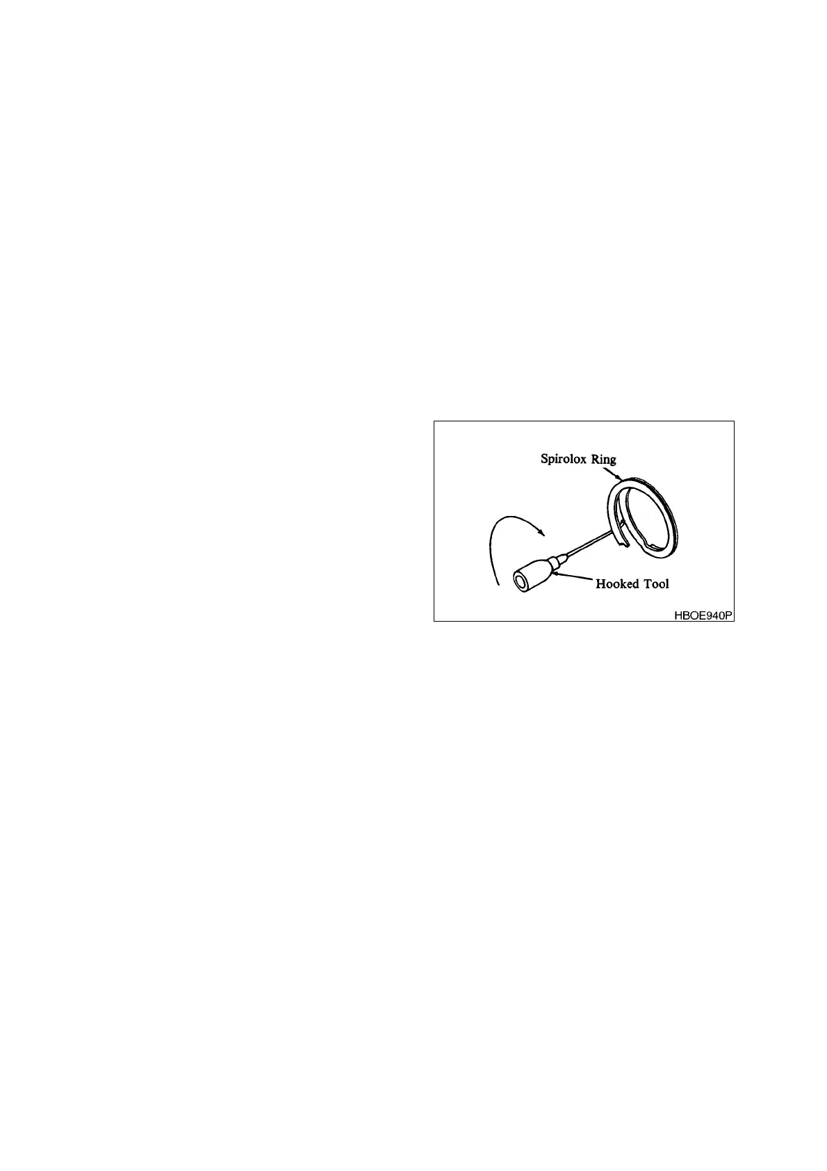
8. Pry under coil and remove spirolox ring (8)
from body (1). (See Figure 6.)
9. Pull the shaft group (items 7, 6, and 5)
from body (1). If bearing (6) or shaft (5)
need replacement, remove retaining ring
(7) with retaining ring pliers. Remove
bearing (6) from shaft (5) by using an arbor
press. Apply pressure to the inner race
when removing bearing.
10. Remove washer (4) and primary shaft seal
(3) from body (1).
11. Drive secondary shaft seal (2) out of
mounting end of body (1).
Figure 6 REMOVING SPIROLOX RING