S0708470K
Page 16
Steering and Brake Pump (Denison T67DB Series)
CLEANING AND INSPECTION (WEAR LIMITS AND
TOLERANCES)
For general cleaning and inspection procedures, refer to "General Maintenance Procedures" section.
CLEANING
All parts must be thoroughly cleaned and kept clean during inspection and assembly. Contamination of unit
will cause excessive wear, leakage, and decreased service life. Use a commercial solvent which is
compatible with the system fluid. Thoroughly clean all parts. Drying parts with compressed air after
cleaning is not recommended, unless the air is completely filtered to remove water and contamination.
INSPECTION, REPAIR AND REPLACEMENT
Check all internal passages. Make sure they are clean and unobstructed. Examine all mating surfaces for
nicks and burrs. Check locating pins and holes for wear and burrs. Check the condition of threaded parts
and threaded holes. Check all snap ring recesses. Minor burrs can be removed with an India stone.
Replace any part which shows wear or damage. The following parts are subject to special attention:
1. Cartridge kits (39 and 40). to obtain
maximum overhaul life of the pump, a
complete cartridge kit should be installed if
wear or scoring is noticed during the
following inspection steps.
A. Inspect the mating surfaces of the
rotors (15 and 28), outlet support
plates (17 and 30), and inlet support
plates (12 and 25) for wear and/or
scoring.
B. Inspect vanes and inserts (16 and
29) for burrs, wear, and play in slots
of rotors (15 and 28). Remove minor
burrs with an India stone.
NOTE:
DO NOT
use a dry stone on
bronze surfaces or scratches will result
C. Inspect bushing for wear and scoring.
2. Check bearing (33) for wear, looseness, and pitted or cracked races.
3. Inspect seal and bushing mating surfaces on the shaft for scoring and wear. Replace shaft if marks
cannot be removed by light polishing.
4. Remove burrs from outer edge of ring (27). Place rotor (15) and ring (27) on a flat surface. Measure
ring/rotor clearance with a dial indicator. Ring/rotor clearance are noted in Table below.
Model Minimum Clearance Limit In Inches
T67DB - 1308 0.018 mm (0.0007 in)
T67DB - 031 0.038 mm (0.0015 in)
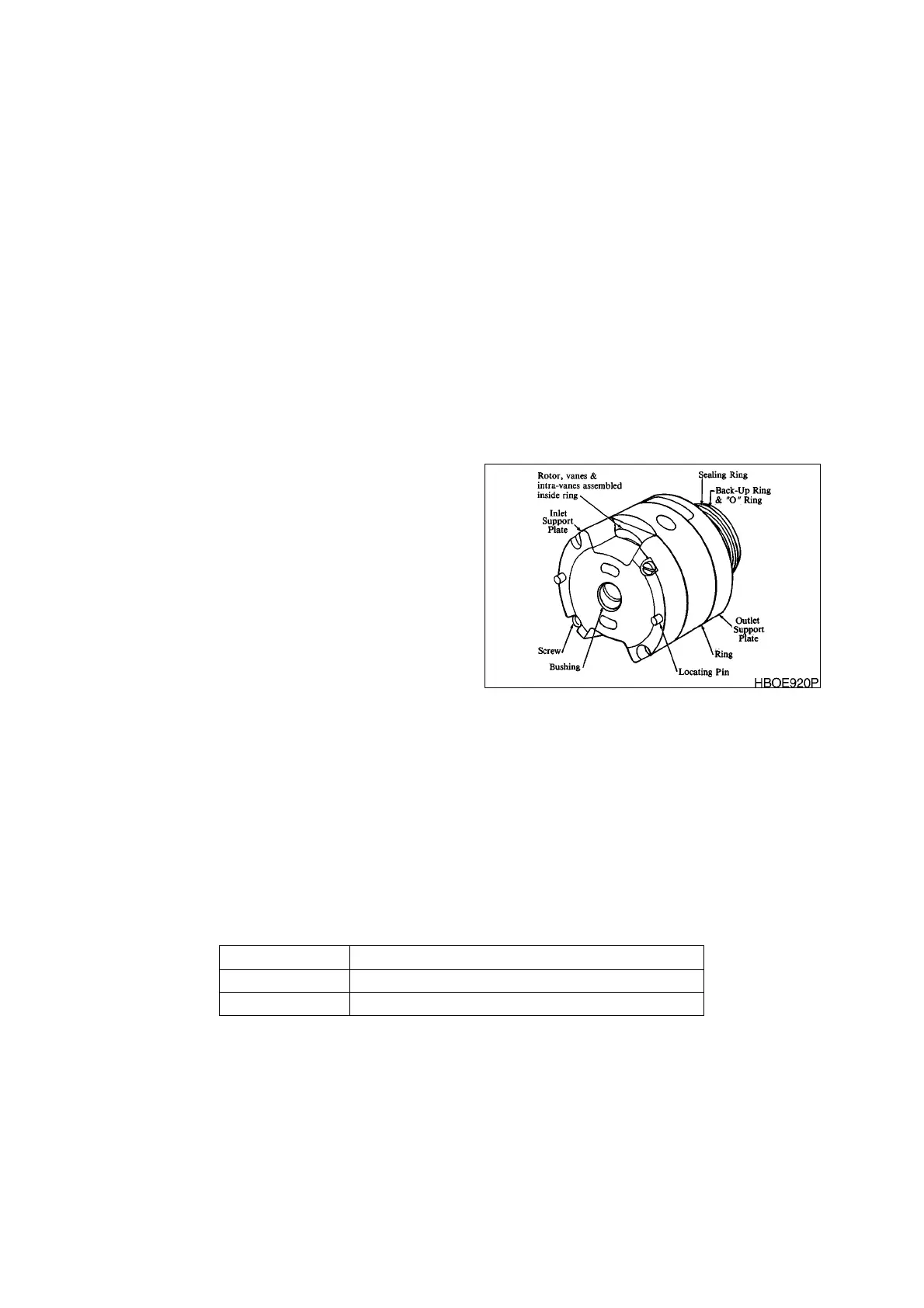
Figure 14 PREASSEMBLED CARTRIDGE