S0802190K
Page 16
Electrical System
Return to Master Table of Contents
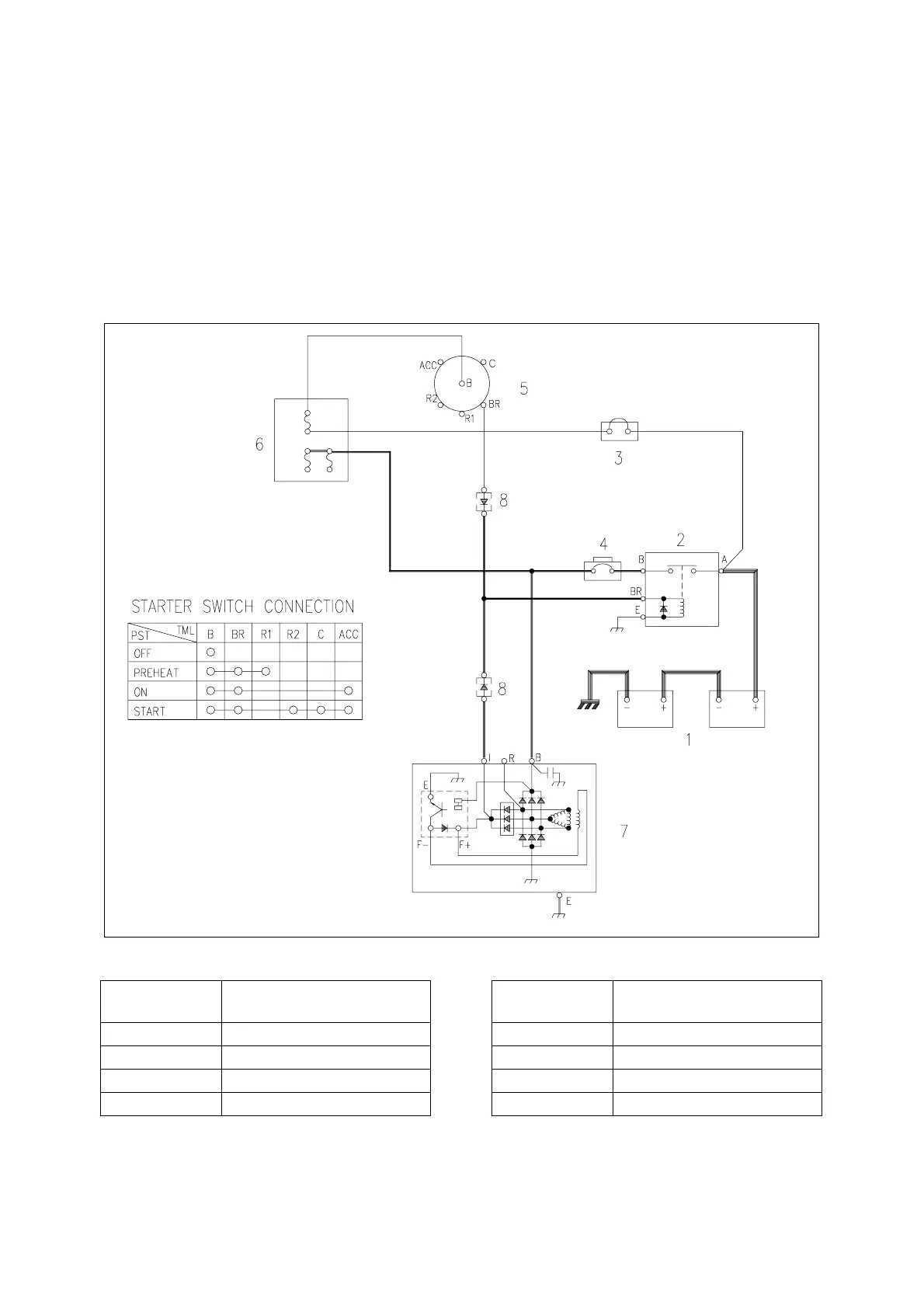
CHARGING SYSTEM
When the starter switch (5) is turned to the "ON" position, an initial excited current flows to the field coil of
the alternator (7) through the battery relay (2) and circuit breaker (4). When the engine is started from this
condition the alternator (7) starts charging. The current flows from the "B+" terminal of alternator (7), to the
circuit breaker (4), to the battery relay (2), and to the battery (1).
The alternator also supplies electric current to other electrical components. When the alternator (7) starts
to operate, a current flows from the "R" terminal of alternator to the diode (8) and then to the battery relay
(2) coil securing a path for the charging current to the battery (1). Thus, preventing the possibility of a high
voltage build up and possible damage to the electrical system.
AHS0080L
Figure 9 CHARGING CIRCUIT
Reference
Number
Description
1 Battery
2 Battery Relay
3 Fusible Link
4 Circuit Breaker
5 Starter Switch
6 Fuse Box
7 Alternator
8 Diode
Reference
Number
Description