S0708470K
Page 3
Steering and Brake Pump (Denison T67DB Series)
GENERAL DESCRIPTION
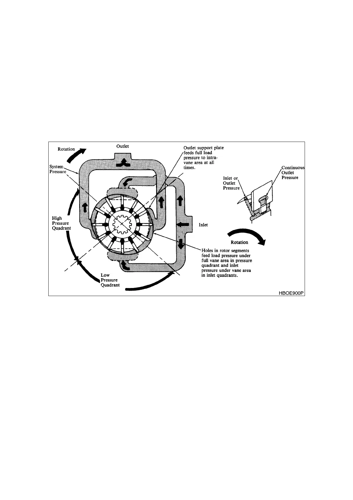
The operating principle of a vane pump is illustrated in Figure 1. A slotted rotor is splined to the drive shaft
and turns inside a cam ring. Vanes are fitted to rotor slots and follow inner surface of cam ring as the rotor
turns. Centrifugal force and pressure under vanes hold them out against the cam ring. Pumping chambers
are formed between the vanes and cam ring and are enclosed by two end plates.
The pump is a balanced intra-vane design. See Figure 1. Outlet pressure is constantly applied to small
intra-vane area of the vane. As the pump vane rotates through high and low quadrants, outlet pressure is
alternately applied to the rest of under vane area. This varying pressure under the vane reduces wear and
increases pump efficiency.
Pump delivery can be changed by changing the ring or installing a new cartridge kit. Cartridge kit part
numbers are tabulated in parts and service drawings.
Figure 1 VANE PUMP OPERATION