S0607080K
Page 5
Transmission and Torque Converter
(ZF 4WG-310)
DRIVE TRAIN DESCRIPTION
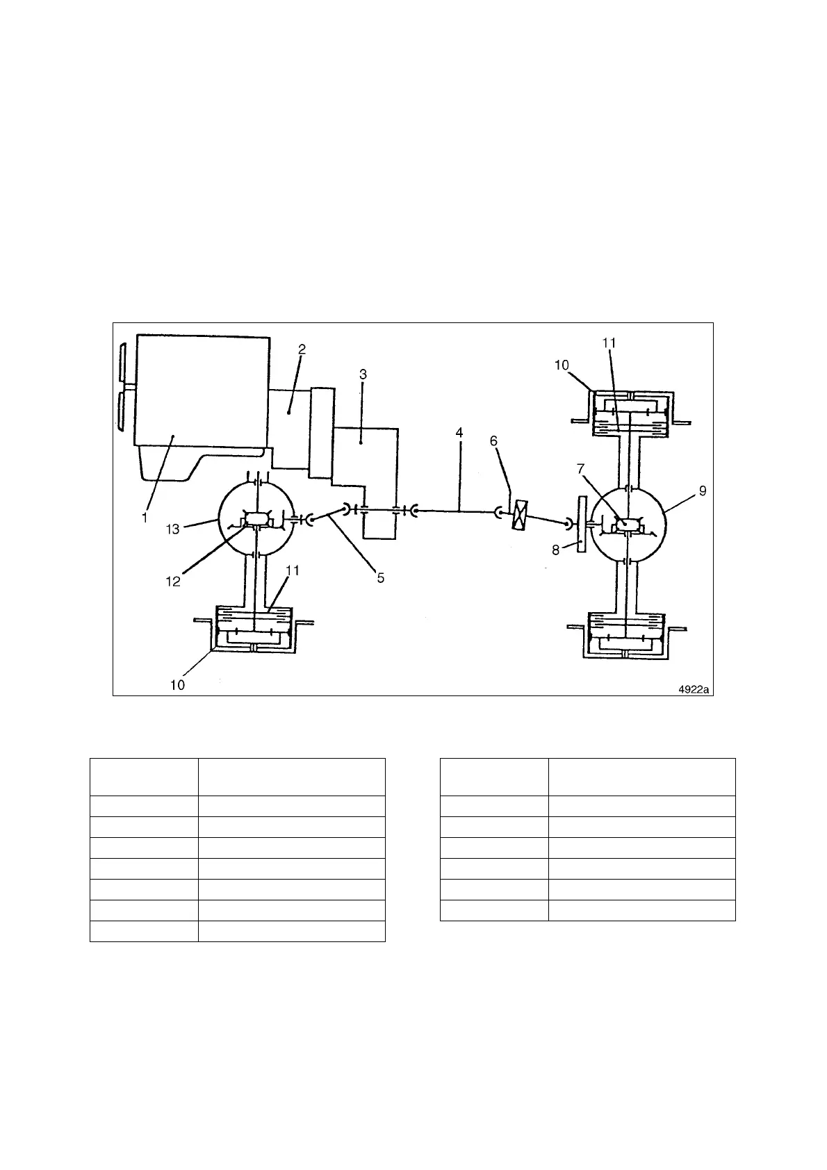
Figure 1, shows layout of drive train assemblies. The engine (1, Figure 1) drives a torque converter (2),
which drives a power shift transmission (3). Two output shafts extend out of the transmission. Each output
shaft has a drive shaft attached to it. Front drive shaft (4) drives a final drive shaft (6) that drives the front
differential (7).
A parking brake (8, Figure 1) is mounted on the front differential input shaft. The front differential is
enclosed in the front axle housing (9). Each end of the front axle housing contains reduction gearing (10).
Each end of the front axle housing also contains a service brake (11). Rear drive shaft (5) drives the rear
differential (12). The rear differential is enclosed in the rear axle housing (13). Each end of the rear axle
housing contains reduction gearing (10). Each end of the rear axle housing also contains a service brake
(11).
Figure 1
Reference
Number
Description
1 Engine
2 Torque Converter
3 Transmission
4 Front Drive Shaft
5 Final Drive Shaft
6 Rear Drive Shaft
7 Front Differential
8 Parking Brake
9 Front Axle Housing
10 Reduction Gearing
11 Service Brake
12 Rear Differential
13 Rear Axle Housing
Reference
Number
Description