S0607080K
Page 97
Transmission and Torque Converter
(ZF 4WG-310)
8. Oil O-rings and piston bearing surfaces.
Insert K2 piston uniformly until contact is
obtained.
NOTE:
Pay attention to the installation
position of the piston, see /
Figure 214.
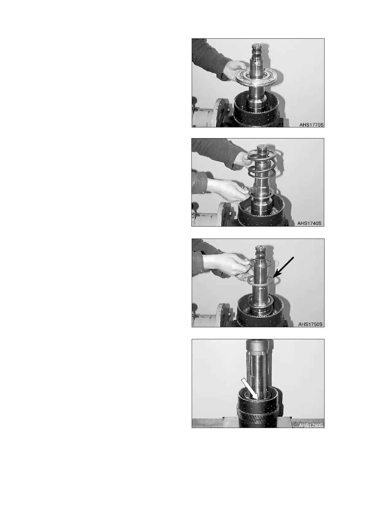
9. Introduce intermediate plate and
compression spring.
10. Lay guide ring, with the chamfer (Arrow)
facing upward, over the compression
spring and line up the snap ring.
11. Lift plate carrier out of the clamping ring
(S). Preload compression spring using
Special device (S) and squeeze snap ring
into the annular groove of the plate carrier
(Arrow), see Figure 217.
12. Install purge valve, spool and compression
spring on the opposite side (KR clutch)
accordingly as Figure 212 - Figure 217.
13. Now, lift plate carrier, with the KR-side
facing downward into the clamping ring (S)
and secure it.
Figure 214
Figure 215
Figure 216
Figure 217