S0708460K
Page 4
Main Pump (Denison T6DMY Series)
Assembly and Construction
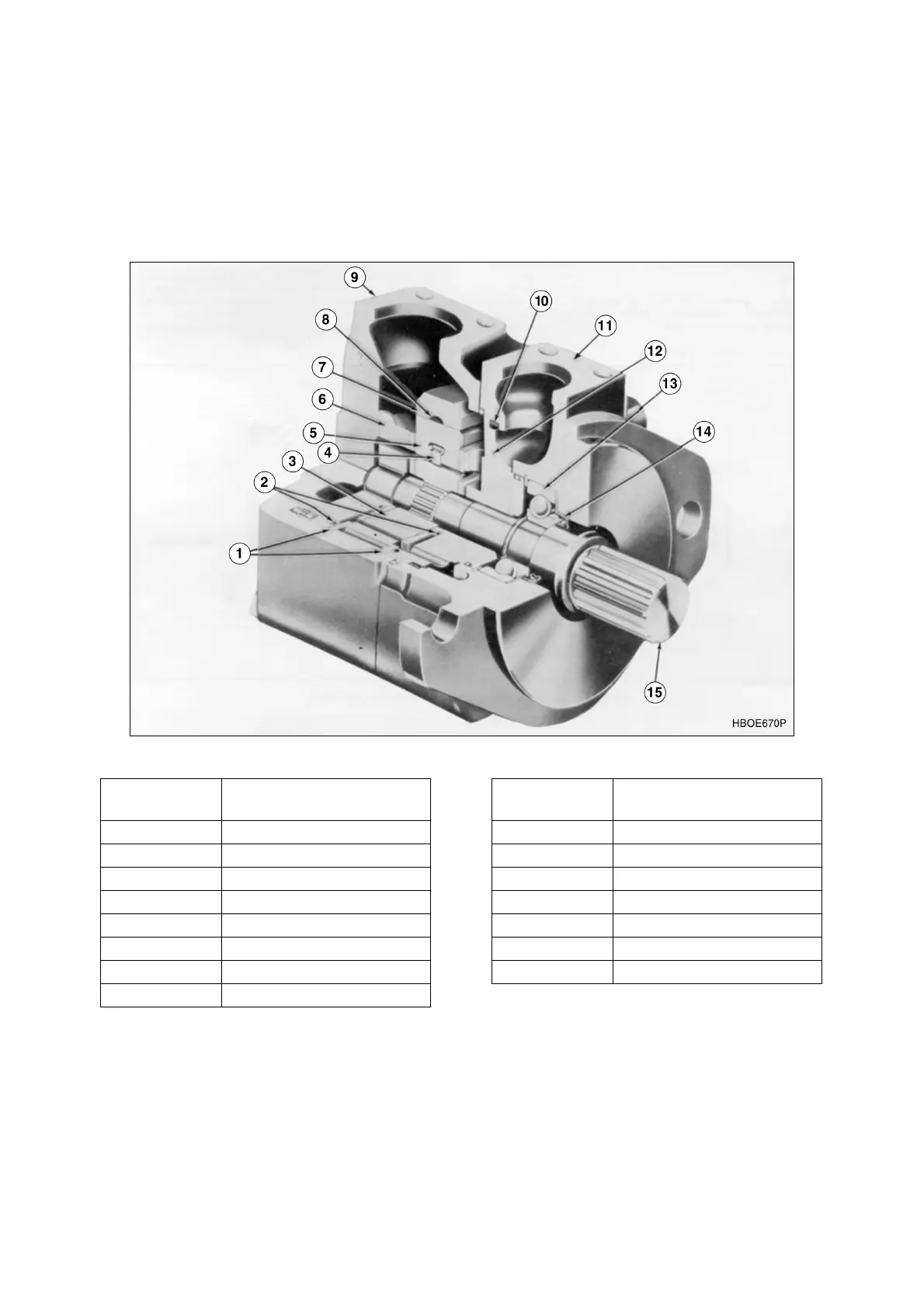
The pump illustrated in Figure 2 is representative of all single pumps in this series. The unit consist
principally of an inlet cover, outlet body, drive shaft and pumping cartridge. The principle components of the
cartridge are an elliptical cam ring, a slotted rotor splined to the drive shaft, an inlet and outlet support
plate fitted with four special seal packs, two flex side plates, and ten vanes and inserts fitted to the rotor
slots. Fluid enters the cartridge through the inlet port in the cover and is discharged through the outlet flex
side plate and support plate to the outlet port in the body.
Figure 2
Reference
Number
Description
1 Flex Side Plates
2 Seal Packs
3 Rotor
4 Insert
5 Vane
6 Inlet Support Plate
7 Ring
8 Inlet Hole Thru Ring
9 Outlet Cover
10 Square Seal Ring
11 Outlet Body
12 Outlet Support Plate
13 Shaft Bearing
14 Primary Seal
15 Shaft
Reference
Number
Description