S0709240K
Page 4
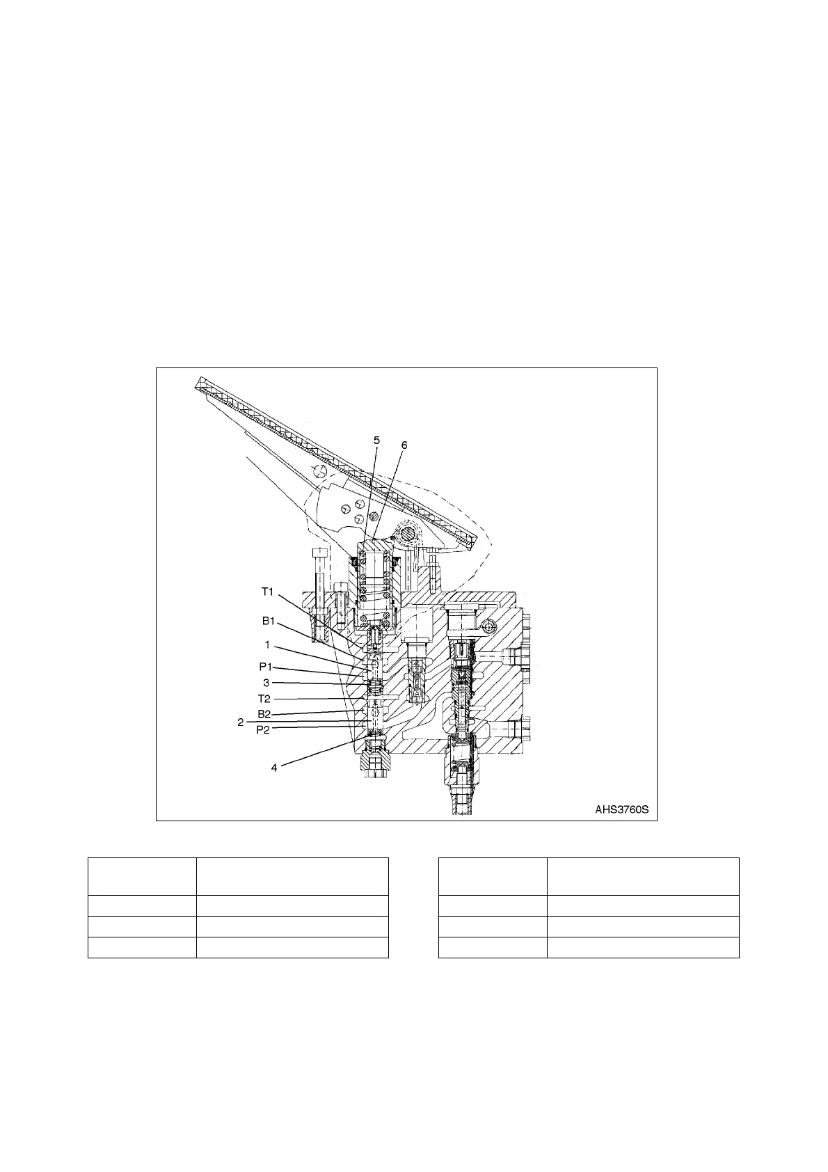
Brake Pedal Valve
When the brake pedal is depressed, force is applied to the working element (6, Figure 2). This force is
transferred to the primary control spool (1) and the secondary control spool (2) by the main control spring
(5). This causes the control spool lands to close the path from the supply ports (P1 and P2) to the tank
ports (T1 and T2). Simultaneously, the spool then opens a path from the brake circuit ports (Br1 and Br2)
to the supply ports (P1 and P2). Drilled passages in control spools (1 and 2) allow fluid pressure in ports
P1 and P2 to act against the main control spring (5). This allows brake pressure in both circuits to rise
proportionally to the force applied to the brake pedal.
As the force applied to the brake pedal becomes constant, the control spools (1 and 2) move into a
balanced position and hold the braking pressure constant.
When force is removed from the brake pedal, this removes force from the control spring. The return
springs (3 and 4) now move the control spools (1 and 2) to the upward. The spools open a path from the
brake circuit ports (B1 and B2) to the tank ports (T1 and T2) and this releases the pressure from the brake
circuits.
Figure 2
Reference
Number
Description
1 Primary Control Spool
2 Secondary Control Spool
3 Lower Spring
4 Upper Spring
5 Main Control Spring
6 Working Element
Reference
Number
Description